
Control of voltage source converters

A technology of voltage source converter and voltage, which is applied in the direction of power transmission AC network, conversion of AC power input to DC power output, circuit device, etc., and can solve problems such as not providing direct flow paths for units

Inactive Publication Date: 2017-12-01
GENERAL ELECTRIC TECH GMBH
View PDF4 Cites 11 Cited by
  • Summary
  • Abstract
  • Description
  • Claims
  • Application Information

AI Technical Summary

Problems solved by technology

In this case, however, the full H-bridge cell does not provide a direct flow path between the terminals of the cell when in the blocking state, and any fault current will have to flow via the cell capacitor whose voltage is used for against current

Method used


Image

  • Control of voltage source converters
  • Control of voltage source converters
  • Control of voltage source converters

Examples


Embodiment Construction

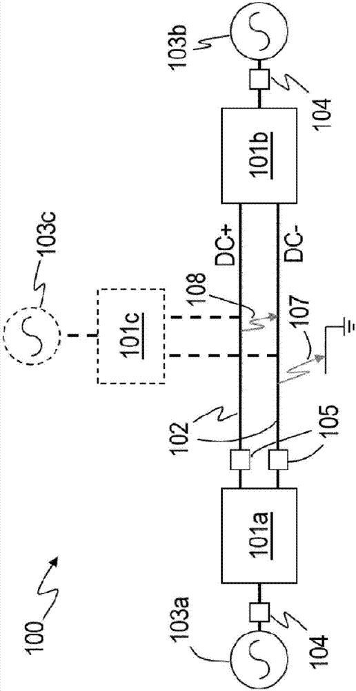
[0061] As mentioned above, a fault-blocking VSC with multiple full H-bridge cells in each inverter leg can be used in a DC network to provide protection against any contribution of AC to the fault current in case of a DC-side fault. block.

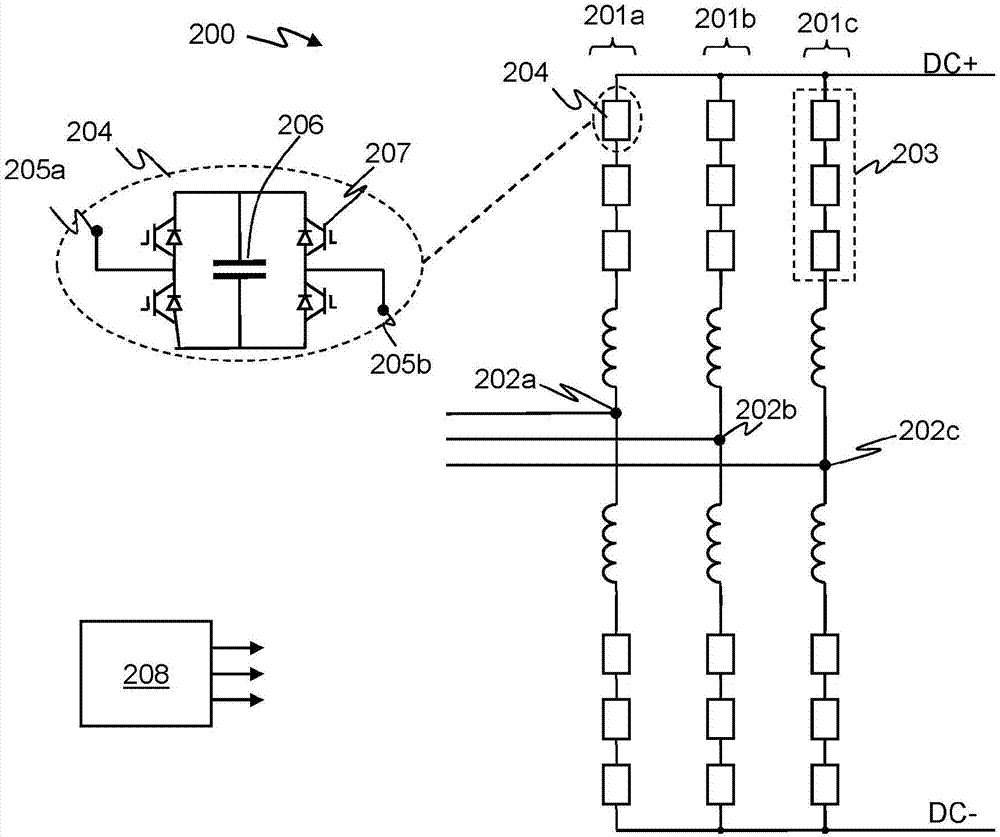
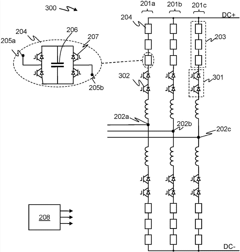
[0062] back to reference figure 2 and 3 , in case of a DC fault, the VSC switches to a blocking state, and in the blocking state, all switching elements 207 of the full-bridge cells are rendered non-conductive. Current can flow via the diode of the switching element 207, but the only flow path for current through the cell is via the energy storage element, ie the capacitor 206, the voltage of which opposes the current.

[0063]Typically, therefore, the controller 208 of a fault blocking VSC 200, 300 may switch the VSC to a blocking state as soon as a DC side fault is identified, ie an indication of a DC side fault is generated or received at the controller. This will relatively quickly block any contribution of AC to the fault current....


PUM


Abstract

This application relates to methods and apparatus for controlling a fault blocking voltage source converter (VSC) apparatus, e.g. a fault blocking VSC (200, 300) with one or one more full bridge cells (204) or a combination of VSCs (1201, 1202) with fault blocking capability. In the event of a DC side interruption, such as a DC side fault, the method involves operating (403, 404) the voltage source converter apparatus after identification (401) of the need for the DC side interruption to extract at least some electrical energy from the connected DC system to the VSC. At least some of the energy extracted from the DC system may be transferred to AC system. Once sufficient energy is extracted from the DC system the VSC may be isolated from the DC system and the voltage source converter apparatus may be switched (406) to a blocked state. Thus rather than instantly switch a fault blocking VSC to the blocked state on detection of a DC side fault the VSC is continued to be operated, and in a manner to transfer at least some energy stored in the DC system to the AC system before blocking.

Description

technical field [0001] The present invention relates to methods and devices for controlling a voltage source converter in the event of a DC side interruption (eg a DC side fault), and in particular to controlling a voltage source converter with fault blocking capability. Background technique [0002] HVDC (High Voltage Direct Current) power transmission uses direct current for power transmission. This is an alternative to the more common AC power transmission. There are many benefits to using HVDC power transmission. HVDC is particularly useful for long-distance power transmission and / or interconnecting alternating current (AC) networks operating at different frequencies. [0003] Until now, most HVDC transmission systems have been based on line-commutated converters (LCCs), such as six-pulse bridge converters using thyristor valves. LCCs use elements such as thyristors, which can be turned on by an appropriate trigger signal and remain conductive as long as they are forw...

Claims


Application Information

Patent Timeline
Patent Type & Authority Applications(China)
IPC IPC(8): H02M1/32H02J3/36H02M7/483
CPCH02J3/36H02M1/32H02M7/483H02J2003/365Y02E60/60H02M7/4835H02M1/0095H02M1/322
Inventor R.古普塔C.巴克R.怀特豪斯A.亚当茨克
Owner GENERAL ELECTRIC TECH GMBH
Learn More