

Circular weaving machine with railing-type shuttle runways
A circular loom and fence type technology, which is applied in the field of circular looms with fence type shuttle runways, can solve the problems of friction and extrusion between rollers and warp threads, and achieve the effect of avoiding thread breakage and saving maintenance costs.
- Summary
- Abstract
- Description
- Claims
- Application Information
AI Technical Summary
Problems solved by technology
Method used
Image

Examples
Embodiment 1
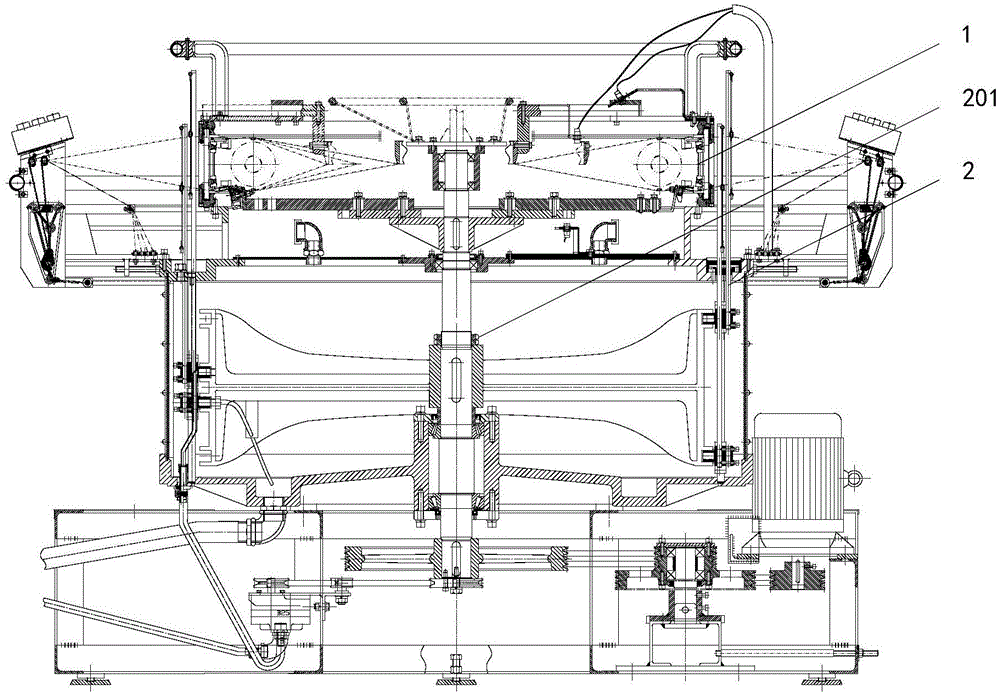
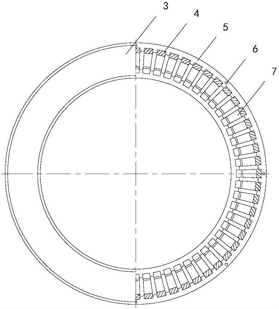
[0025] Such as Figure 1 to Figure 3 As shown, a circular loom with a fence-type shuttle runway described in the embodiment of the present invention, the fence-type shuttle runway 1 is fixed on the frame 2, the machine shuttle 10 is connected to the main shaft 201, and the upper surface of the lower door ring 5 passes through The cutting process has a plurality of first fixing grooves 9, and the lower surface of the upper door ring 3 has a plurality of second fixing grooves 8 through cutting, and the opening of each first fixing groove 9 and the opening of each second fixing groove 8 are one by one. Correspondingly, and jointly used to fix the same grid plate 4, the upper end of the grid plate 4 is stuck in the second fixing groove 8, and the lower end of the grid plate 4 is stuck in the first fixing groove 9, which can be quickly positioned and installed, and each Each grid plate 4 can be replaced independently, reducing maintenance costs. The lower door ring 5 and the upper...
Embodiment 2
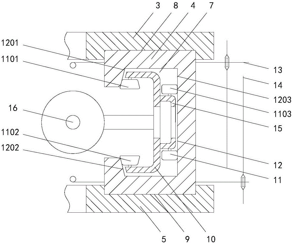
[0029] Such as Figure 4 As shown in the embodiment of the present invention, a circular loom with a fence-type shuttle runway, the third support surface 1203 includes an upper slope 1204 and a lower slope 1205 with opposite inclination directions, and the upper slope 1204 is connected to the top surface of the groove 7 The place is an obtuse angle, and the joint of the bottom surface of the remaining groove 7 on the lower slope 1205 is an obtuse angle. The upper slope 1204 and the lower slope 1205 apply two vertical component forces in opposite directions to the machine shuttle 10, and the vertical direction of the machine shuttle 10 is reversed. Limiting, the third roller 1103 includes an upper tapered roller 1104 and a lower tapered roller 1105 in contact with the upper inclined surface 1204 and the lower inclined surface 1205, and the tapered roller can keep in close contact with the inclined surface. Wherein the junction of the top surface of the upper slope 1204 and the ...
Embodiment 3
[0032] Such as Figure 5 As shown, the embodiment of the present invention has a circular loom with a fence-type shuttle runway, the first support surface 1201 is a slope, the first roller 1101 is a tapered roller, the third support surface 1203 is a slope, and the third roller 1103 is Tapered roller, the tapered roller can maintain close contact with the inclined surface, the inclination direction of the first support surface 1201 and the third support surface 1203 is the same, the angle between the first support surface 1201 and the top surface of the groove 7 is an obtuse angle, the third support surface The included angle between the surface 1203 and the bottom surface of the groove 7 is an obtuse angle. The first support surface 1201 and the third support surface 1203 have two component forces in opposite directions in the vertical direction, and the two component forces act together on the shuttle 10. Up, limit the vertical direction of machine shuttle 10. The angle bet...
PUM
 Abstract
Description
Claims
Application Information