Electric connector

An electrical connector and conductivity technology, applied in the field of electrical connectors, can solve the problems of increasing the processing difficulty of signal terminals and grounding parts, weakening the anti-interference ability of signal transmission, and affecting the shielding effect of electrical connectors, so as to enhance the anti-interference ability , prevent short circuit, reduce the effect of processing difficulty

Active Publication Date: 2017-12-05
DEYI PRECISION ELECTRONIC IND CO LTD PANYU
View PDF5 Cites 15 Cited by
  • Summary
  • Abstract
  • Description
  • Claims
  • Application Information

AI Technical Summary

Problems solved by technology

[0003] However, in order to prevent the signal terminals from short-circuiting against the shield, the signal terminals are not provided with the extension portion abutting against the shield, so that the structure of the signal terminals is different from that of the ground. In actual production, the processing difficulty of the signal terminal and the grounding piece is increased, and during assembly, the operator easily assembles the signal terminal into the storage tube where the grounding piece is located by mistake, so that it does not abut against the shielding piece, Affects the shielding effect of the electrical connector and weakens the anti-interference ability during signal transmission

Method used


Image

  • Electric connector
  • Electric connector
  • Electric connector

Examples


Embodiment Construction

[0033] In order to facilitate a better understanding of the purpose, structure, features, and effects of the present invention, the present invention will now be further described in conjunction with the accompanying drawings and specific embodiments.

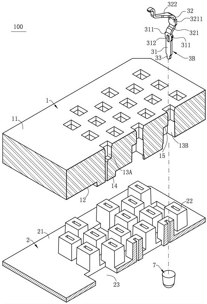
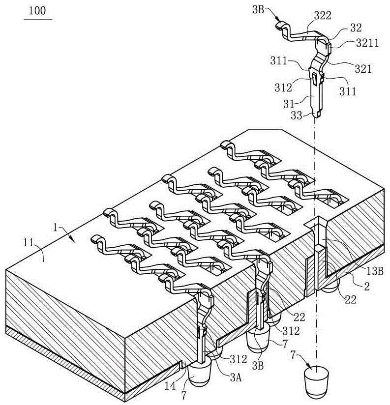
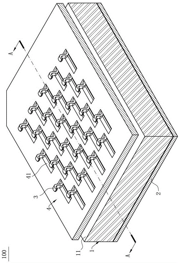
[0034] Such as Figure 1 to Figure 7 It is the electrical connector 100 of the first embodiment of the present invention, which is used to electrically connect a chip module 5 to a circuit board 6, which includes: an insulating member 2; a body 1 located on the insulating member 2; The body 1 and the insulator 2 have a plurality of signal terminals 3B and ground terminals 3A with the same structure, the signal terminals 3B are used to contact the signal pads of the chip module 5, and the ground terminals 3A are used to contact the ground pads of the chip module 5 piece.

[0035] Such as figure 1 and figure 2 As shown, the body 1 has an upper surface 11 and a lower surface 12 oppositely arranged, and a plurality of grounding...


PUM


Abstract

The invention discloses an electric connector, which comprises a body, an insulated piece, multiple signal terminals and multiple grounding terminals, wherein the body is provided with multiple grounding accommodating holes and multiple signal accommodating holes which pass through the body vertically, and the inner side walls of the grounding accommodating holes and the signal accommodating holes are conductive; the insulated piece and the body are formed in a separated mode, and the insulated piece is provided with multiple convex parts accommodated in the signal accommodating holes only corresponding to the signal accommodating holes; each signal terminal is provided with at least one positioning part correspondingly positioned on the convex part, and thus, the signal terminal and the signal accommodating hole are not contacted; the grounding terminals and the signal terminals have the same structure, the grounding terminals are accommodated in the grounding accommodating holes correspondingly, the inner side wall of each grounding accommodating hole is provided with a contact area contacted with the positioning part of the grounding terminal, and the height of the contact area is between the highest point and the lowest point of the convex part. Thus, the processing difficulty and the assembling difficulty of the grounding terminal and the signal terminal can be reduced, the shielding effects of the electric connector are ensured, and the anti-interference ability in the case of signal transmission is enhanced.

Description

technical field [0001] The invention relates to an electrical connector, in particular to an electrical connector electrically connecting a chip module to a circuit board. Background technique [0002] The Chinese patent with the patent number CN201020663926.6 discloses an electrical connector, including an insulating body, a plurality of signal terminals, a grounding element and a plurality of shielding elements. The insulating body is provided with a plurality of receiving tubes, each The signal terminals are correspondingly accommodated in one of the accommodating tubes, and a plurality of the shielding members are stacked and assembled into the insulating body, each of the shielding members is provided with a plurality of shielding holes, and each of the shielding members is The hole is correspondingly arranged on the periphery of a storage tube, and a slot is provided on the storage tube where the grounding piece is located, and the grounding piece has an extension part...

Claims


Application Information

Patent Timeline
Patent Type & Authority Applications(China)
IPC IPC(8): H01R12/71H01R13/02H01R13/40H01R13/502H01R13/648H01R33/74
CPCH01R12/716H01R13/02H01R13/40H01R13/502H01R13/648H01R33/74H05K2201/10265H01R13/2442H01R13/6471H01R13/6588H01R13/6597H05K3/3426H05K2201/10424H05K2201/10189H05K2201/10318Y02P70/50H01R13/6581H01R12/57H01R12/714H01R13/646
Inventor 朱德祥何建志金左锋
Owner DEYI PRECISION ELECTRONIC IND CO LTD PANYU
Why Eureka
Try Eureka