Artificial hip joint

A hip joint prosthesis and artificial technology, applied in the direction of hip joints, joint implants, joint implants, etc., can solve the problems of shortening the service life of artificial hip joint prosthesis, artificial hip joint loosening, adverse biological reactions, etc. , to avoid the risk of secondary surgery, reduce surgical trauma, and high wear resistance

Active Publication Date: 2017-12-08
JILIN UNIV FIRST HOSPITAL
View PDF14 Cites 6 Cited by
  • Summary
  • Abstract
  • Description
  • Claims
  • Application Information

AI Technical Summary

Problems solved by technology

It can be seen that materials such as ultra-high molecular weight polyethylene have a service life, and they also face the danger of failure after being implanted in the human body. Many problems are caused by wear and tear; the accumulation of wear debris and induce a series of adverse biological reactions in the soft tissue, which makes the well-fixed artificial hip joint loose and greatly shortens the service life of the artificial hip joint prosthesis, so that most patients cannot No revision surgery

Method used


Image

  • Artificial hip joint
  • Artificial hip joint
  • Artificial hip joint

Examples


Embodiment 1

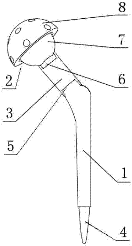
[0025] Such as figure 1 As shown, the artificial hip joint prosthesis includes a femoral stem 1, a femoral ball head 2, and an elastic connector 3. The distal end 4 of the femoral stem 1 can be inserted into the femoral medullary cavity, and the proximal end 5 of the femoral stem extends laterally and upwardly. In the natural state, the angle between the axis of the extension end and the axis of the femoral stem is 110°-140°, and the end of the extension end suddenly becomes thinner into a step shape, and the thin section extends 6-10 mm upward to the side for fixing the elastic connector 3, One end of the elastic connector 3 is inserted into the thin section and leans against the step, the other end of the elastic connector 3 is connected to the femoral ball head 2, and the connection between the femoral ball head and the elastic connector 3 has a columnar protrusion 6 with a length of 6-10 mm. The columnar protrusion 6 realizes the fixed connection between the elastic connec...

Embodiment 2

[0032] Such as figure 1 As shown, most of the structure of the artificial hip joint prosthesis of the present invention is the same as that of Embodiment 1, the difference is that the elastic connector 3 in this embodiment is a cylindrical elastic metal, and its hollow structure can save materials and ensure Sufficient elasticity is required, and it is fixedly connected with the femoral stem 1 and the femoral ball head 2 at both ends respectively through interference fit. In addition, the elastic connector 3 can also be equipped with a locking mechanism, and 2-3 inward protrusions are provided near the end, and 2-3 inward protrusions are provided at the corresponding connecting positions of the femoral stem 1 and the femoral ball head 2 . The groove is used to lock with the protrusion on the elastic connector 3. The elastic connecting member 3 can also be fixedly connected by clamping, welding and other connection methods.

Embodiment 3

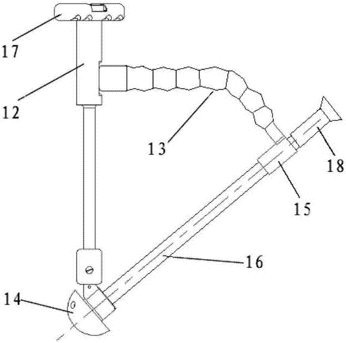
[0034] The present invention also provides a replacement device for implanting the aforementioned artificial hip joint prosthesis into the human body, such as image 3 As shown, the replacement device has a joystick 12, a guiding telescopic rod 13, an acetabular cup connector 14, a sleeve 15 and an acetabular cup knocking rod 16, the proximal end of the joystick 12 has a fixedly connected handle 17, and the distal end The acetabular cup connector 14 is connected, and a guiding telescopic rod 13 is fixedly connected under the handle. The other end of the guiding telescopic rod is provided with a sleeve 15. The sleeve is used to insert the acetabular cup knocking rod 16. The guiding telescopic rod 13 has a certain Elasticity and support, can be bent, stretched and shortened in all directions, so as to adjust the distance between the sleeve 15 and the acetabular cup connector 14 according to the needs, and make the two aligned for easy installation, which needs to be adjusted in a...


PUM

PropertyMeasurementUnit
thicknessaaaaaaaaaa
thicknessaaaaaaaaaa

Abstract

The invention provides an artificial hip joint prosthesis which is flexible in adjustment, capable of meeting movement requirements in each direction and high in wear resistance of related contact surfaces to solve technical problems. An implanting tool is improved to reduce operation wounds. The artificial hip joint prosthesis comprises a femoral stem, a femoral bulb and an elastic connector. A far end of the femoral stem can be inserted in a femoral marrow cavity, a near end of the femoral stem extends upwards laterally, an included angle between the axis of an extending end and the axis of the femoral stem under a natural state is 110-140 degrees, the end of the extending end is suddenly thinned into a step shape, a thin section extends upwards laterally by 6-10mm and is used for fixing the elastic connector, one end of the elastic connector is inserted into the thin section and abutted against the step position while the other end of the elastic connector is connected with the femoral bulb, and the joint of the femoral bulb and the elastic connector is provided with a column projection 6-10mm in length. Therefore, arbitrary adjustment of the artificial hip joint prosthesis in each angle is realized, and especially adjustment of a front inclination angle and a collodiaphyseal angle at a sagittal view and a coronal view is realized.

Description

technical field [0001] The invention relates to the field of joint prosthesis, in particular to an artificial hip joint prosthesis. Background technique [0002] In recent years, with the application and popularization of artificial hip replacement, osteoarthritis, rheumatoid arthritis, aseptic necrosis of the femoral head, traumatic arthritis, congenital acetabular dysplasia and other diseases have gradually been effectively treated And improvement, artificial hip replacement surgery has become the most effective way to treat hip diseases. The artificial hip joint prosthesis used in this operation includes the femoral prosthesis and the acetabular cup prosthesis, among which the firmness and stability of the acetabular cup prosthesis, and the adaptability of the femoral prosthesis and acetabular cup to the natural bone structure of the human body , is a key factor affecting the life and safety of artificial hip prosthesis. At present, more integrated designs or articulate...

Claims


Application Information

Patent Timeline
Patent Type & Authority Applications(China)
IPC IPC(8): A61F2/32A61F2/34A61F2/36
CPCA61F2/32A61F2/34A61F2/36A61F2/3609A61F2/3662A61F2002/30329A61F2002/30426A61F2002/30451A61F2002/30462A61F2002/30476A61F2002/3611A61F2002/3615A61F2002/365A61F2310/00574
Inventor 丁普刘宽浩范炎峰丁玉
Owner JILIN UNIV FIRST HOSPITAL
Why Eureka
Try Eureka