Lubricating oil preparation mixing machine for automobile engine

A technology for automobile engine and lubricating oil, which is applied in mixers, shaker/oscillation/vibration mixers, mixers with rotary stirring devices, etc., can solve the problems of short time and long time.

Inactive Publication Date: 2017-12-08
赵雅萱
View PDF8 Cites 2 Cited by
  • Summary
  • Abstract
  • Description
  • Claims
  • Application Information

AI Technical Summary

Problems solved by technology

[0006] In order to overcome the disadvantages in the prior art that the preparation cannot be carried out under airtight conditions, only one-way rotation can be carried out for stirring and mixing, and the preparation takes a long time, the technical problem to be solved by the present invention is to provide a Preparation, multi-directional rotation for stirring and mixing, and preparation of lubricants for automobile engines with short preparation time

Method used


Image

  • Lubricating oil preparation mixing machine for automobile engine
  • Lubricating oil preparation mixing machine for automobile engine
  • Lubricating oil preparation mixing machine for automobile engine

Examples


Embodiment 1

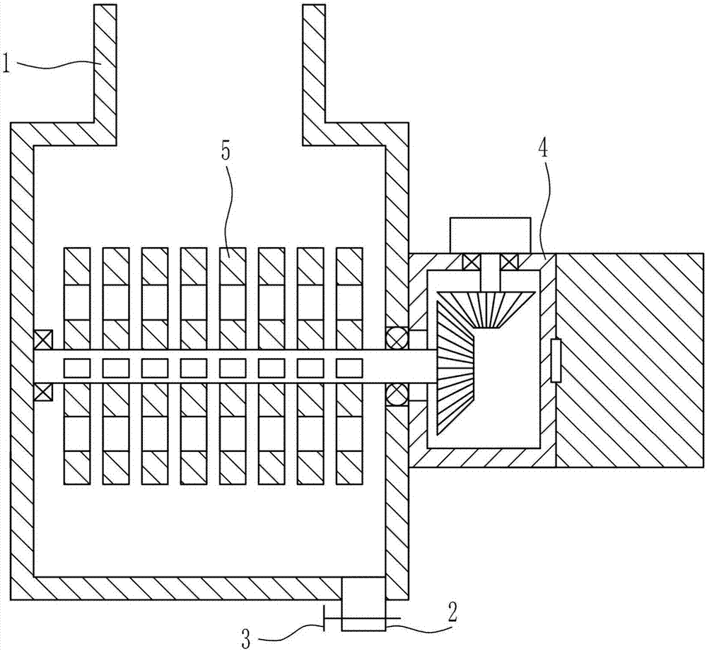
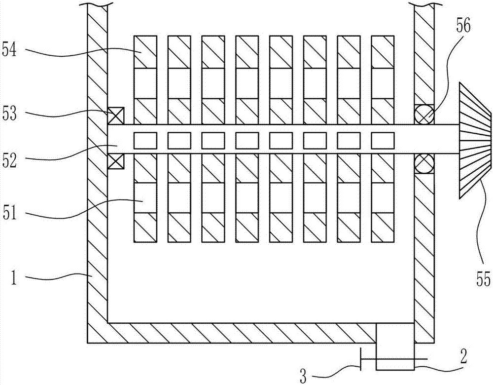
[0030] A kind of lubricating oil preparation mixer for automobile engine, such as Figure 1-5 As shown, it includes a mixing box 1, a discharge pipe 2, a valve 3, a driving mechanism 4 and a mixing mechanism 5. The bottom right side of the mixing box 1 is connected with a discharge pipe 2, and a valve 3 is arranged on the discharge pipe 2. The mixing box 1 is provided with a mixing mechanism 5, and the middle part on the right side of the mixing box 1 is connected with a driving mechanism 4, and the driving mechanism 4 is connected with the mixing mechanism 5.

Embodiment 2

[0032] A kind of lubricating oil preparation mixer for automobile engine, such as Figure 1-5 As shown, it includes a mixing box 1, a discharge pipe 2, a valve 3, a driving mechanism 4 and a mixing mechanism 5. The bottom right side of the mixing box 1 is connected with a discharge pipe 2, and a valve 3 is arranged on the discharge pipe 2. The mixing box 1 is provided with a mixing mechanism 5, and the middle part on the right side of the mixing box 1 is connected with a driving mechanism 4, and the driving mechanism 4 is connected with the mixing mechanism 5.

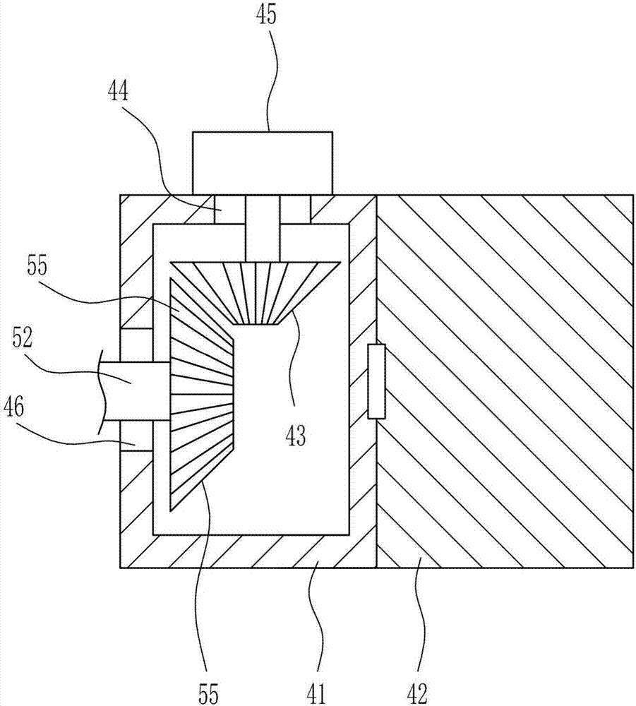
[0033]The driving mechanism 4 includes an installation box 41, a case cover 42, a first bevel gear 43 and a motor 45. The middle part of the right side of the mixing box 1 is connected with an installation box 41, and the right side of the installation box 41 is connected with a box cover 42 by means of a hinge connection. , the middle part of the bottom wall of the installation box 41 has a first through hole 44, the ...

Embodiment 3

[0035] A kind of lubricating oil preparation mixer for automobile engine, such as Figure 1-5 As shown, it includes a mixing box 1, a discharge pipe 2, a valve 3, a driving mechanism 4 and a mixing mechanism 5. The bottom right side of the mixing box 1 is connected with a discharge pipe 2, and a valve 3 is arranged on the discharge pipe 2. The mixing box 1 is provided with a mixing mechanism 5, and the middle part on the right side of the mixing box 1 is connected with a driving mechanism 4, and the driving mechanism 4 is connected with the mixing mechanism 5.

[0036] The driving mechanism 4 includes an installation box 41, a case cover 42, a first bevel gear 43 and a motor 45. The middle part of the right side of the mixing box 1 is connected with an installation box 41, and the right side of the installation box 41 is connected with a box cover 42 by means of a hinge connection. , the middle part of the bottom wall of the installation box 41 has a first through hole 44, the...


PUM


Abstract

The invention relates to a mixing machine and particularly relates to a lubricating oil preparation mixing machine for an automobile engine. The invention aims at providing a lubricating oil preparation mixing machine for an automobile engine, which can be used for preparing lubricating oil in an airtight condition and can perform stirring and mixing through multidirectional rotation and realizes low time consumption in preparation. To achieve the aim, the invention provides the lubricating oil preparation mixing machine for the automobile engine, which comprises a mixing box and the like, wherein the right side of the bottom of the mixing box is connected with a discharge pipe; a valve is arranged on the discharge pipe; a mixing mechanism is arranged in the mixing box; the right middle of the mixing box is connected with a drive mechanism; the drive mechanism is connected with the mixing mechanism. According to the invention, through arranging the drive mechanism and the mixing mechanism, the purpose of carrying out stirring and mixing preparation on the raw materials in the mixing box is realized.

Description

technical field [0001] The invention relates to a mixer, in particular to a mixer for preparing lubricating oil for automobile engines. Background technique [0002] Automobile is a vehicle that can be driven by its own power, and can be driven by motor without the need for rails or electric power. In a broad sense, a vehicle with four wheels is generally called a car. An engine is a machine that can convert other forms of energy into mechanical energy, including internal combustion engines, external combustion engines, electric motors, etc. For example, internal combustion engines usually convert chemical energy into mechanical energy. The engine is not only applicable to the power generating device, but also refers to the whole machine including the power device. The engine was first born in the UK, so the concept of the engine also comes from English, and its original meaning refers to the mechanical device that generates power. [0003] Since the existing process of ...

Claims


Application Information

Patent Timeline
Patent Type & Authority Applications(China)
IPC IPC(8): B01F7/04B01F11/00B01F15/02
CPCB01F27/0722B01F27/11251B01F27/074B01F27/191B01F27/70B01F31/441B01F35/7173B01F35/7547B01F2101/39
Inventor 赵雅萱
Owner 赵雅萱
Why Eureka
Try Eureka