Hydraulic machine

A technology for hydraulic presses and blank holders, applied in the field of hydraulic presses, can solve problems such as structural redundancy of hydraulic presses, and achieve the effects of simple structure, reduced weight, and easy installation and disassembly

Inactive Publication Date: 2017-12-08
JIANGSU GREENHUB TECH
View PDF0 Cites 0 Cited by
  • Summary
  • Abstract
  • Description
  • Claims
  • Application Information

AI Technical Summary

Problems solved by technology

[0003] The technical problem to be solved by the present invention is to provide a hydraulic press, which solves the problem that the general hydraulic press cylinder is installed on the slider structure and connected with the blanking beam, resulting in redundant structure of the overall hydraulic press

Method used


Image

  • Hydraulic machine
  • Hydraulic machine

Examples


Embodiment Construction

[0018] The following embodiments may enable those skilled in the art to fully understand the present invention, but they do not limit the present invention to the scope of the described embodiments.

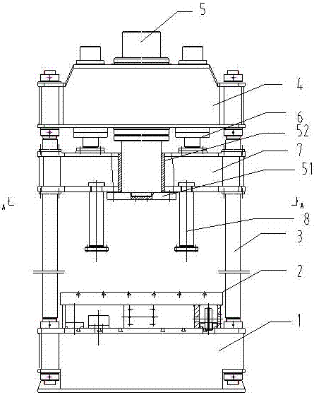
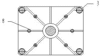
[0019] Such as figure 1 figure 2 The hydraulic press shown includes a workbench 1, a mobile platform 2, a column 3, an upper beam 4, a main cylinder 5, a blanking cylinder 6 and a blanking beam 7.

[0020] The workbench 1 is arranged horizontally, and the upper surface of the workbench 1 is provided with guide rails that cooperate with the mobile platform 2, and the mobile platform 2 moves on the workbench 1 through the guide rails.

[0021] The uprights 3 are vertically arranged at the corners of the worktable 1 along the vertical direction.

[0022] The upper beam 4 is arranged on the top end of the column 3, the master cylinder 5 is arranged on the upper beam 4, and a pair of blanking cylinders 6 are respectively arranged on both sides of the master cylinder 5.

[0023] The blank hold...


PUM


Abstract

The invention relates to a hydraulic machine, which is characterized in that it includes a workbench, a mobile platform, a column, an upper beam, a main cylinder, a blank holder cylinder and a blank holder beam; in the present invention, the binder cylinder is directly connected to the blank holder beam , avoiding the use of sliders, which makes the structure of the entire hydraulic machine simpler, easy to install and disassemble, and also reduces the overall weight of the hydraulic machine; The block ensures the displacement accuracy of the piston rod of the master cylinder and precisely controls the stroke of the piston rod of the master cylinder.

Description

Technical field [0001] The invention relates to the field of hydraulic presses, in particular to a hydraulic press. Background technique [0002] In the hydraulic press, the blank holder cylinder used in the general blank holder is connected to a slide block arranged above the blank holder beam, and the blank holder cylinder is arranged on the slide block to drive the movement of the blank holder beam. As a result, the slider used on the hydraulic press increases the redundancy of the hydraulic press and increases the weight of the entire hydraulic press. Summary of the invention [0003] The technical problem to be solved by the present invention is to provide a hydraulic press, which solves the problem that the general press cylinder is installed on the sliding block structure and connected with the press beam to cause the redundancy of the overall hydraulic press structure. [0004] In order to solve the above technical problems, the technical solution of the present invention i...

Claims


Application Information

Patent Timeline
Patent Type & Authority Applications(China)
IPC IPC(8): B30B1/32B30B15/04
CPCB30B1/32B30B15/04
Inventor 王华
Owner JIANGSU GREENHUB TECH
Why Eureka
Try Eureka