
a gasifier

A gasifier and exhaust port technology, which is applied in the field of gasifiers, can solve the problems of too many semi-coke particles and increase the burden of gas-solid separation devices, and achieve the effect of reducing dust content and reducing dust removal burden.

Active Publication Date: 2020-05-12
ENN SCI & TECH DEV
View PDF4 Cites 0 Cited by
  • Summary
  • Abstract
  • Description
  • Claims
  • Application Information

AI Technical Summary

Problems solved by technology

However, since the coal used in the coal hydrogasification reaction is coal powder, the semi-coke particles produced by the gasification reaction have a small particle size and good followability, and are easily entrained by the synthesis gas into the subsequent system. There are more semi-coke particles discharged from the gasifier, which increases the burden on the subsequent gas-solid separation device

Method used


Image

  • a gasifier
  • a gasifier
  • a gasifier

Examples


Embodiment Construction

[0029] The following will clearly and completely describe the technical solutions in the embodiments of the present invention with reference to the accompanying drawings in the embodiments of the present invention. Obviously, the described embodiments are only some, not all, embodiments of the present invention. Based on the embodiments of the present invention, all other embodiments obtained by persons of ordinary skill in the art without making creative efforts belong to the protection scope of the present invention.

[0030] In describing the present invention, it is to be understood that the terms "center", "upper", "lower", "front", "rear", "left", "right", "vertical", "horizontal", The orientations or positional relationships indicated by "top", "bottom", "inner", "outer", etc. are based on the orientations or positional relationships shown in the drawings, and are only for the convenience of describing the present invention and simplifying the description, rather than in...


PUM


Abstract

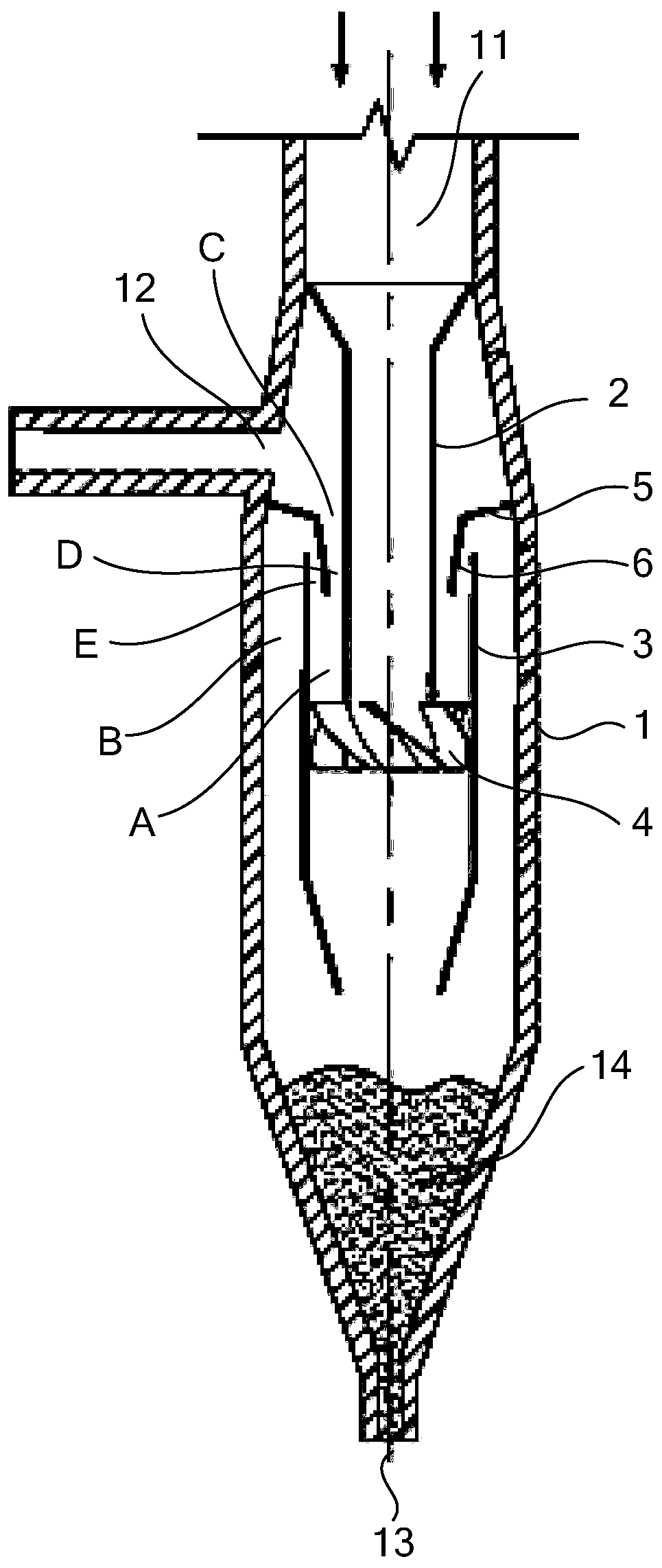
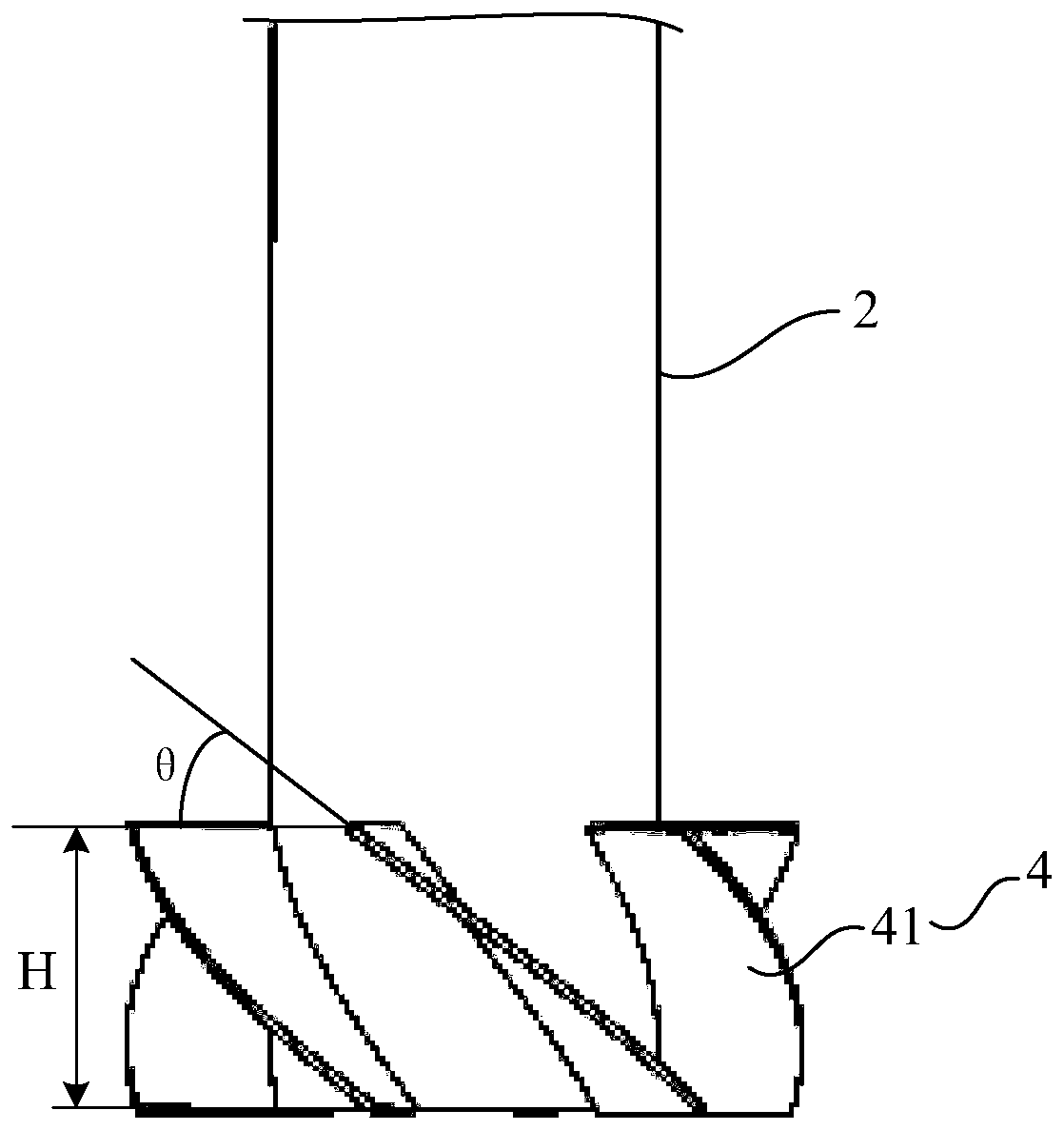
The invention discloses a gasification furnace and relates to the technical field of coal gasification equipment. It was invented to solve the problem that the content of semi-coke particles in the synthesis gas discharged from the existing gasifier is relatively large, and the burden of subsequent gas-solid separation is relatively heavy. The gasification furnace of the present invention includes a shell, the top wall of the shell is provided with a raw material inlet, the side wall of the shell is provided with an exhaust port, the bottom wall of the shell is provided with a coke discharge port, and the shell is provided with a built-in guide. Flow tube, swirl inner tube and swirl member, one end of the built-in flow guide tube communicates with the raw material inlet, and the other end extends downward; the swirl inner tube is sleeved outside the lower end of the built-in flow guide tube, and the swirl inner tube The upper end extends upwards to a position close to the exhaust port, a first annular gap is formed between the inner wall of the swirl inner cylinder and the built-in guide tube, and a second annular gap is formed between the outer wall of the swirl inner cylinder and the inner wall of the housing ; The swirl component is arranged between the lower end of the built-in guide tube and the swirl inner tube. The gasification furnace of the invention is used for coal hydrogenation gasification reaction.

Description

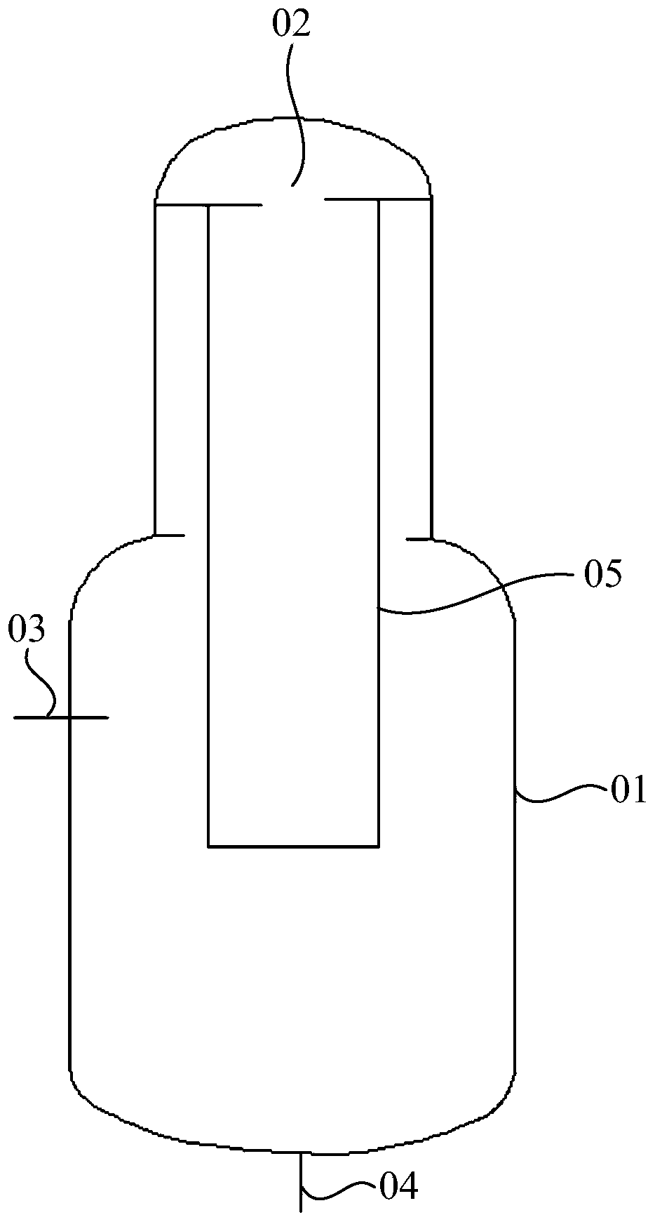
technical field [0001] The invention relates to the technical field of coal gasification equipment, in particular to a gasification furnace. Background technique [0002] At present, one of the more commonly used technologies in coal gasification technology is coal hydrogenation gasification, and coal hydrogenation gasification is usually figure 1 shown in the gasifier, see figure 1 , the gasifier includes a shell 01, the top wall of the shell 01 is provided with a raw material inlet 02, the side wall of the shell 01 is provided with an exhaust port 03, and the bottom wall of the shell 01 is provided with a coke discharge port 04, The casing 01 is provided with a built-in guide tube 05, one end of the built-in guide tube 05 communicates with the raw material inlet 02, and the other end extends downward. In this way, coal and gasification agent enter the built-in guide tube 05 from the raw material inlet 02, and coal hydrogenation gasification reaction occurs in the built-i...

Claims


Application Information

Patent Timeline
Patent Type & Authority Patents(China)
IPC IPC(8): C10J3/00C10J3/72C10J3/74
CPCC10J3/007C10J3/72C10J3/74C10J2300/093C10J2300/0966
Inventor 孙中卫聂永广马志超刘泽龙
Owner ENN SCI & TECH DEV
Learn More