Device and method for purifying flue gases

A flue gas purification and flue gas technology, applied in chemical instruments and methods, separation methods, electrostatic effect separation, etc., can solve the problems of low nitric oxide oxidation efficiency, difficulty in bipolar discharge, etc. Abrasion, effect of low dust concentration

Inactive Publication Date: 2016-06-08
CHNA ENERGY INVESTMENT CORP LTD +1
View PDF7 Cites 11 Cited by
  • Summary
  • Abstract
  • Description
  • Claims
  • Application Information

AI Technical Summary

Problems solved by technology

[0004] The purpose of the present invention is to overcome the defect of low nitric oxide oxidation efficiency in the existing flue gas purification technology, and to provide a device and method for flue gas purification, which can efficiently oxidize nitric oxide in flue gas to carbon dioxide Nitrogen and strong charging of fine particulate matter smoke, and effective removal of nitrogen dioxide and residual smoke in downstream equipment
At the same time, due to the difficulty of bipolar discharge under high particle concentration, the oxidation efficiency of nitric oxide is low

Method used


Image

  • Device and method for purifying flue gases
  • Device and method for purifying flue gases
  • Device and method for purifying flue gases

Examples


Embodiment 1

[0057] This embodiment is used to illustrate the device and method for purifying flue gas provided by the present invention.

[0058] (1) Construction of the device

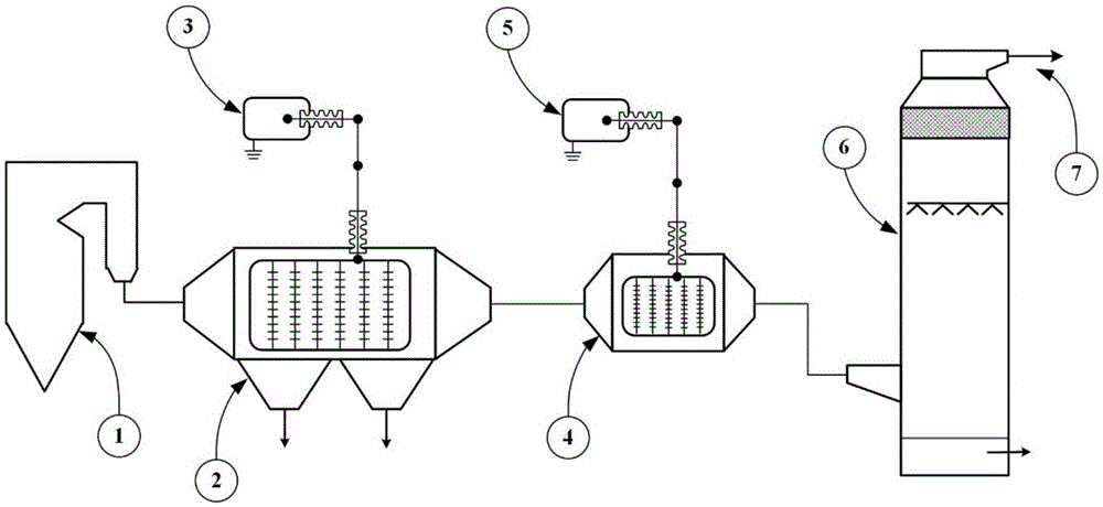
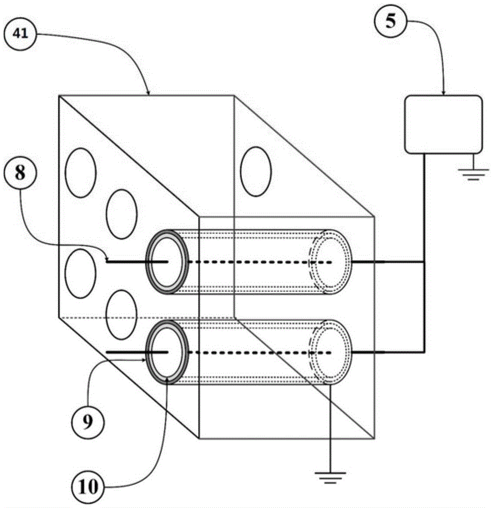
[0059] Connect boiler 1, electrostatic precipitator 2, dielectric barrier discharge reactor 41, and wet desulfurization equipment 6 sequentially, the outlet of dielectric barrier discharge reactor 41 is connected to the inlet of the absorption tower of wet desulfurization equipment 6, and electrostatic precipitator 2 is connected to The first high-voltage power supply 3 (single-phase DC high-voltage power supply), the dielectric barrier discharge reactor 41 is connected to the second high-voltage power supply 5 (ZH2006 pulse high-voltage power supply, peak voltage 60kV, discharge frequency 300Hz), and the flue gas is installed on the wet desulfurization equipment 6. Gas outlet 7. get figure 1 The flue gas cleaning device shown.

[0060] (2) Flue gas purification

[0061] according to figure 1 The flue gas de...

Embodiment 2

[0065] This embodiment is used to illustrate the device and method for purifying flue gas provided by the present invention.

[0066] (1) Construction of the device

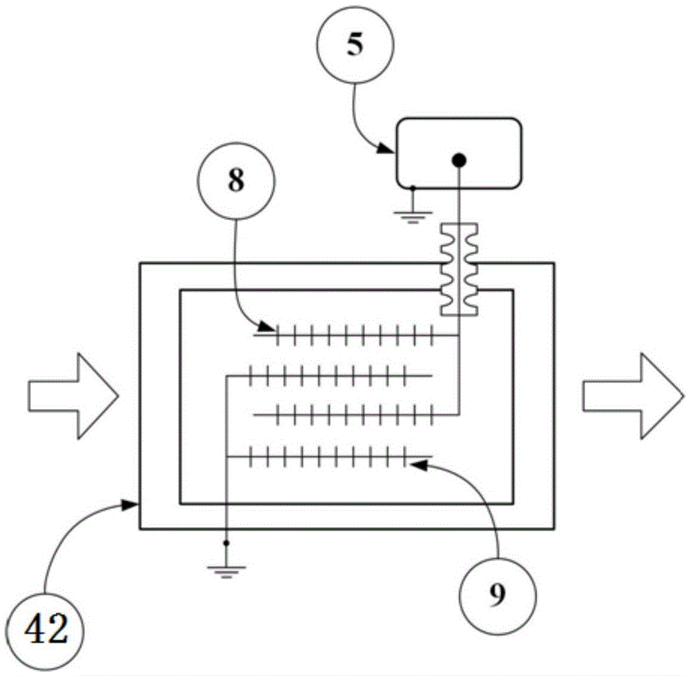
[0067] Connect boiler 1, electrostatic precipitator 2, streamer corona discharge reactor 42, and wet desulfurization equipment 6 sequentially, the outlet of streamer corona discharge reactor 42 is connected to the inlet of the absorption tower of wet desulfurization equipment 6, and the electrostatic precipitator 2 Connect the first high-voltage power supply 3 (three-phase DC high-voltage power supply), and the streamer corona discharge reactor 42 is connected to the second high-voltage power supply 5 (bipolar DC high-voltage power supply, the negative polarity discharge is 72kV, and the positive polarity discharge is 60kV). The flue gas outlet 7 is set on the wet desulfurization equipment 6 . get figure 1 The flue gas cleaning device shown.

[0068] (2) Flue gas purification

[0069] according to figure 1 T...


PUM


Abstract

low-temperaturetes to the field of flue gas treatment and discloses a device and a method for purifying flue gases. The device for purifying the flue gases comprises an electrical precipitator (2), a low-temperature plasma reactor (4) and wet desulphurization equipment (6) which are connected in sequence, wherein an outlet of the electrical precipitator (2) is connected with an inlet of the low-temperature plasma reactor (4); an outlet of the low-temperature plasma reactor (4) is connected with an inlet of the wet desulphurization equipment (6). The method for purifying the flue gases comprises the following steps of introducing the flue gases containing dust and nitrogen oxide into the electrical precipitator (2) for performing dust removing treatment; enabling the flue gases subjected to the dust removing treatment to enter into the low-temperature plasma reactor for oxidation treatment; then introducing the flue gases formed by the oxidation treatment into the wet desulphurization equipment for absorption treatment. By adopting the device and the method disclosed by the invention, the oxidation and dust charging efficiency of nitric oxide is high; the device is not easy to wear and is good in purifying effect of the flue gases.

Description

technical field [0001] The invention relates to the field of flue gas treatment, in particular to a device and method for purifying flue gas. Background technique [0002] Flue gas is one of the main emissions of thermal power plants, which is produced by burning combustibles in burners (ie, boilers). Because flue gas usually contains a large amount of nitrogen oxides NO x Such as NO, if these nitrogen oxides are directly discharged into the atmosphere, it will cause highly corrosive acid rain, so the flue gas must be removed from the nitrogen oxides before being discharged. [0003] There are two main reaction pathways for the removal of nitrogen oxides in flue gas: nitrogen oxide reduction and nitric oxide (NO) oxidation, nitrogen dioxide (NO 2 )absorb. In the invention patent application with the publication number CN102059050A, a method for controlling flue gas composite pollutants is disclosed, in which a bipolar discharge device is used in conjunction with an electr...

Claims


Application Information

Patent Timeline
Patent Type & Authority Applications(China)
IPC IPC(8): B01D53/32B03C3/00
CPCB01D53/32B03C3/00
Inventor 肖创英王仕龙徐会军闫克平韩平
Owner CHNA ENERGY INVESTMENT CORP LTD
Why Eureka
Try Eureka