Vaporizing combustion turbulence incinerator

An incinerator and turbulent flow technology, applied in the field of gasification combustion turbulent flow incinerator, can solve the problems of high gasification temperature for catalytic hydrogen production or alcohol production, low direct utilization rate, complex equipment structure, etc., to achieve uniform and controllable reaction, Small dust content and high burnout rate

Pending Publication Date: 2018-11-06
BEIJING ONE A HI TECH ENERGY TECH CO LTD
View PDF7 Cites 13 Cited by
  • Summary
  • Abstract
  • Description
  • Claims
  • Application Information

AI Technical Summary

Problems solved by technology

However, whether it is combustion or pyrolysis gasification utilization, there are often problems of low direct utilization and secondary pollution.
However, the gasification temperature of catalytic hydrogen production or alcohol production is high and the process is complex
Similarly, most gasification and melting combustion process systems also use high-temperature gasification and high-temperature melting technology, which consumes a lot of energy and complex equipment structure

Method used


Image

  • Vaporizing combustion turbulence incinerator
  • Vaporizing combustion turbulence incinerator

Examples


Embodiment Construction

[0018] The specific embodiment of the present invention and working process will be further described below in conjunction with accompanying drawing.

[0019] The orientation terms such as up, down, left, right, front and rear in this application document are established based on the positional relationship shown in the drawings. If the drawings are different, the corresponding positional relationship may also change accordingly, so this should not be understood as limiting the scope of protection.

[0020] The gasification combustion turbulent flow incinerator described in the present invention is suitable for the gasification and combustion of multiple industrial wastes disposed at the same time.

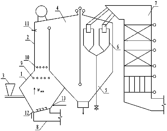
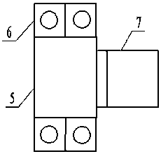
[0021] Such as figure 1 As shown, a gasification combustion turbulent flow incinerator includes a gasification combustion chamber, a burnout section 4 , a cooling section 5 , a separator 6 , a tail flue 7 and a feed device 3 . The gasification combustion chamber communicates wit...


PUM


Abstract

A vaporizing combustion turbulence incinerator comprises a vaporizing combustor, a burning-out section, a cooling section, a separator, a tail smoke flue and a feeding device, wherein the vaporizing combustor communicates with the upper portion of the burning-out section, the burning-out section communicates with the bottom of the cooling section to form a steering separation chamber, the upper portion of the cooling section is connected with an inlet of the separator, and a smoke outlet of the separator communicates with the tail smoke flue. The vaporizing combustor comprises a variable-section vaporizing section and a constant-section combustion section which are integrally arranged. The vaporizing section is provided with a gradually-expanding area and a gradually-contracting area in sequence from bottom to top, and the top of the gradually-contracting area is connected with the combustion section. A slag discharge channel is arranged on one side of the bottom of the vaporizing section. A plurality of secondary air ports and / or a plurality of tertiary air ports are arranged in the middle of the vaporizing combustor, the multiple secondary air ports are evenly arranged in the topof the vaporizing section in a surrounding mode, and the multiple tertiary air ports are evenly arranged in the bottom of the combustion section in a surrounding mode. The vaporizing combustion turbulence incinerator has the advantages of good fuel adaptability, good initial discharging property and high burning-out rate.

Description

technical field [0001] The invention relates to a gasification combustion turbulent flow incinerator, which is used for gasification and combustion of wastes such as plastics and waste tires, and belongs to the field of gasification combustion. Background technique [0002] The resource utilization of industrial waste such as plastics, waste tires, and waste rubber has been widely concerned. [0003] The heat treatment and resource utilization of plastics, waste tires, waste rubber and other industrial wastes include combustion and pyrolysis gasification. Because the calorific value of this kind of waste is generally high, it has high energy utilization value. However, whether it is combustion or pyrolysis gasification utilization, there are often problems of low direct utilization rate and secondary pollution. However, the gasification temperature of catalytic hydrogen production or alcohol production is high and the process is complicated. Similarly, most gasification a...

Claims


Application Information

Patent Timeline
Patent Type & Authority Applications(China)
IPC IPC(8): F23G5/027F23G5/14F23G5/44F23G5/46F23J15/02F23J15/06F23L9/00
CPCF23G5/027F23G5/14F23G5/44F23G5/46F23J15/022F23J15/06F23L9/00F23G2209/28F23G2206/10F23G2201/40
Inventor 陈宣张凝曹剑胡彦霞
Owner BEIJING ONE A HI TECH ENERGY TECH CO LTD
Why Eureka
Try Eureka