
A Zero Blind Spot Ranging System

A ranging system and zero-blind zone technology, applied in radio wave measurement systems, measuring devices, instruments, etc., can solve problems such as large environmental impact, large TOF ranging blind zone, poor anti-interference ability, etc., and achieve high signal-to-noise ratio , echo stabilization and linear effect

Active Publication Date: 2019-09-06
KEENON ROBOTICS CO LTD
View PDF2 Cites 0 Cited by
  • Summary
  • Abstract
  • Description
  • Claims
  • Application Information

AI Technical Summary

Problems solved by technology

[0003] The technical problem to be solved by the present invention is to provide a zero-blind-zone ranging system, which solves the problems of the existing TOF ranging blind zone, slow update speed, and poor anti-interference ability due to environmental influences.

Method used


Image

  • A Zero Blind Spot Ranging System

Examples


Embodiment Construction

[0035] The present invention will be further described below with reference to the accompanying drawings and embodiments, and the mode of the present invention includes but not limited to the following embodiments.

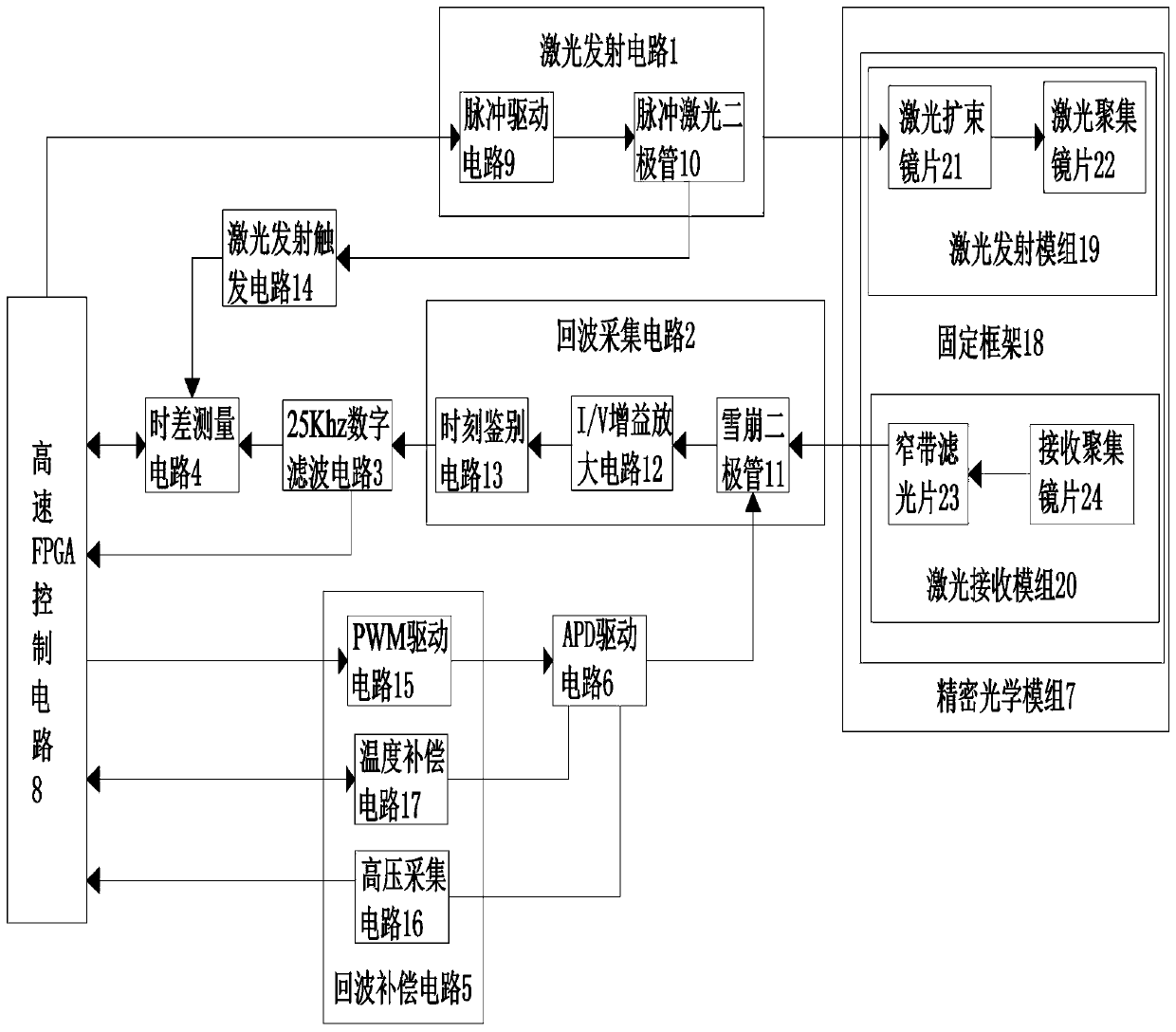
[0036] Such as figure 1 As shown, a zero-blind zone ranging system provided by the present invention has the characteristics of high-speed drive, zero-blind zone measurement, high signal-to-noise ratio, high-precision ranging, ultra-high-speed measurement frequency, and human eye safety. Recognition and super anti-sunlight ability. The present invention includes a laser emission circuit 1, an echo acquisition circuit 2, a laser emission trigger circuit 14, a 25Khz digital filter circuit 3, a time difference measurement circuit 4, an echo compensation circuit 5, an APD drive circuit 6, a precision optical module 7, and A high-speed FPGA control circuit 8 that generates high-precision differential narrow pulse signals and a PWM frequency with an adjustable duty cyc...


PUM


Abstract

The invention discloses a zero-blind area range finding system which addresses large TOF range finding blind area, slow updating speed, susceptibility to great environment influence and poor anti-interference capability in the prior art. According to the invention, the system herein includes a laser emitting circuit, an echo acquiring circuit, a laser emitting triggering circuit, a 25 Khz digital filtering circuit, a time difference measurement circuit, an echo compensating circuit, an APD drive circuit, a precision optical module, and a high speed FPGA control circuit which may generate a high precision difference narrow pulse signal and a PWM frequency signal which has adjustable 25 Khz duty ratio. According to the invention, the system has the characteristics of high speed drive, zero-blind area measurement, high signal-to-noise ratio, high precision range finding, super-high speed measurement frequency, and no eye damage. The system also has the advantages of high environment identification and super-high sunlight resistance capabilities.

Description

technical field [0001] The invention relates to a zero-blind zone ranging system. Background technique [0002] With the development of laser technology and TOF, high-speed, low blind zone, and precise measurement have become indispensable measurement equipment in the market. At present, the blind zone of TOF ranging products in the world is about 15cm-60cm (the farther the distance is, the bigger the blind zone is), and as the speed increases, the blind zone will continue to increase. The zero blind zone ranging system is different from the traditional laser ranging system. Compared with the measurement accuracy, blind spot detection, measurement frequency and distance are more advantageous, not only in the simplification of cost and volume, but also can quickly obtain high-precision distance information with zero blind spots. It is an indispensable and important component in the lidar industry. Contents of the invention [0003] The technical problem to be solved by th...

Claims


Application Information

Patent Timeline
Patent Type & Authority Patents(China)
IPC IPC(8): G01S17/10
Inventor 冉银春郭忠华孙家强余江孙长征
Owner KEENON ROBOTICS CO LTD
Learn More