
Artificial rib connecting structure

A technology for connecting structures and ribs, applied in bone implants, medical science, prostheses, etc., can solve the problems of poor stability and low assembly efficiency, and achieve the effect of strengthening stability and improving efficiency

Pending Publication Date: 2017-12-12
大连派思益科技有限公司
View PDF10 Cites 1 Cited by
  • Summary
  • Abstract
  • Description
  • Claims
  • Application Information

AI Technical Summary

Problems solved by technology

[0003] In the prior art, the assembly efficiency between artificial bone and human bone is low and the stability is poor

Method used


Image

  • Artificial rib connecting structure
  • Artificial rib connecting structure

Examples


Embodiment Construction

[0013] In order to make the purpose, technical solutions and advantages of the embodiments of the present invention clearer, the technical solutions in the embodiments of the present invention will be clearly and completely described below in conjunction with the drawings in the embodiments of the present invention. Obviously, the described embodiments It is a part of embodiments of the present invention, but not all embodiments. Based on the embodiments of the present invention, all other embodiments obtained by persons of ordinary skill in the art without creative efforts fall within the protection scope of the present invention.

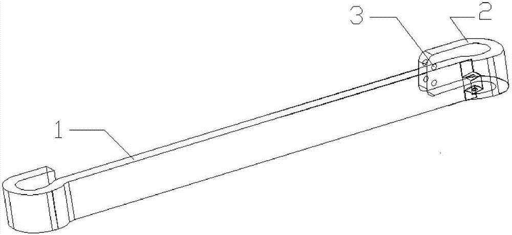
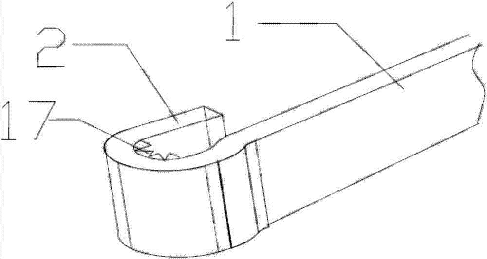
[0014] figure 1 It is a schematic diagram of the connecting structure of the artificial rib of the present invention, as figure 1 As shown, the connection structure of the artificial rib of the present embodiment can include:

[0015] Buckle 2, one end of the buckle 2 is hinged to one end of the artificial rib 1, and the other end is provided wi...


PUM


Abstract

The invention provides an artificial rib connecting structure. The artificial rib connecting structure comprises a buckle, wherein one end of the buckle is hinged to one end of an artificial rib; a through hole is formed in the other end of the buckle; and a bolt is fixedly connected with a vertebra or a sternum through the through hole. By the buckle which is hinged to one end of the artificial rib, the problem that a mode of connecting an artificial bone with a human skeleton in the prior art is low in efficiency is solved. The artificial rib assembling efficiency is improved, and the stability of connection between the artificial rib and the human skeleton is improved.

Description

technical field [0001] The invention relates to the technical field of artificial bones, in particular to an artificial rib connection structure. Background technique [0002] Rib defects in the human body can cause abnormal breathing, seriously affect human health, and even endanger life. Therefore, it is necessary to replace or repair the defective sternum rib. [0003] In the prior art, the assembly efficiency between the artificial bone and the human bone is low and the stability is poor. Contents of the invention [0004] The invention provides an artificial rib connection structure to overcome the above technical problems. [0005] A connection structure of an artificial rib according to the present invention, comprising: [0006] Buckle, one end of the buckle is hinged with one end of the artificial rib, and the other end is provided with a through hole, and the bolt is fixedly connected with the vertebra or the sternum through the through hole. [0007] Further...

Claims


Application Information

Patent Timeline
IPC IPC(8): A61F2/28A61F2/30
CPCA61F2/28A61F2/30767A61F2002/30621
Inventor 张久文王克峰苗延巍张子蜀王佳扬赵盼杨平
Owner 大连派思益科技有限公司
Learn More