Hybrid test method based on vector finite element and FPGA

A hybrid test and finite element technology, applied in the field of hybrid test based on vector finite element and FPGA, can solve problems such as limiting the real-time application range of hybrid test, high computational pressure on numerical substructures, and inability to realize real-time effects.

Active Publication Date: 2017-12-12
ZHEJIANG UNIV
View PDF4 Cites 15 Cited by
  • Summary
  • Abstract
  • Description
  • Claims
  • Application Information

AI Technical Summary

Problems solved by technology

However, such simplification greatly limits the scope of application of real-time mixing experiments.
For those structural systems with uniform mass distribution, such as cables, dams, long-span bridges, etc., the mechanical behavior of the numerical substructure must adopt a sufficient number of degrees of freedom to achieve accurate simulations, which makes real-time substructure tests often difficult due to numerical Computational pressure on substructure parts is too high for real-time effects
[0004] In summary, how to effectively solve the technical problem that real-time results cannot be achieved due to the excessive calculation pressure of the numerical substructure when performing mixed tests on the mass distribution system structure with a large number of degrees of freedom in the numerical substructure is currently a problem for those skilled in the art. Known and Urgently Needed Problems

Method used


Image

  • Hybrid test method based on vector finite element and FPGA
  • Hybrid test method based on vector finite element and FPGA
  • Hybrid test method based on vector finite element and FPGA

Examples


Embodiment Construction

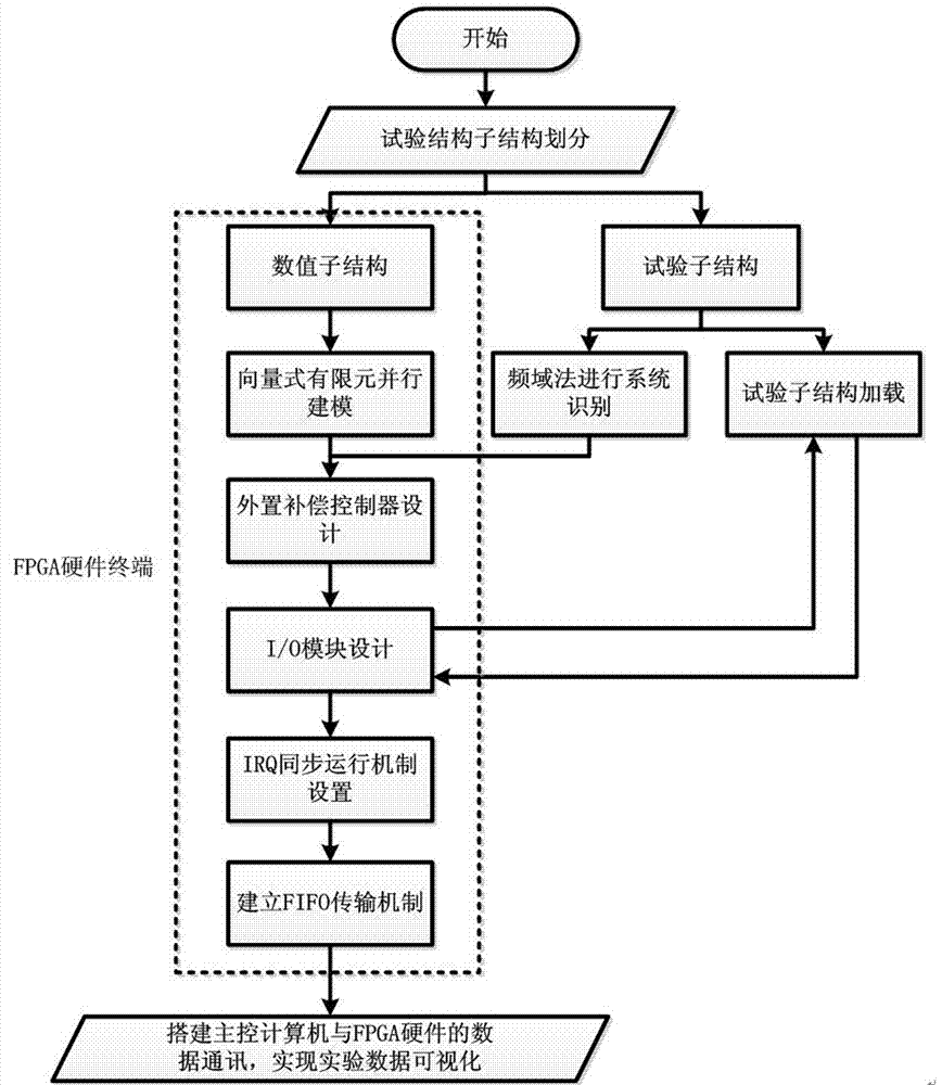
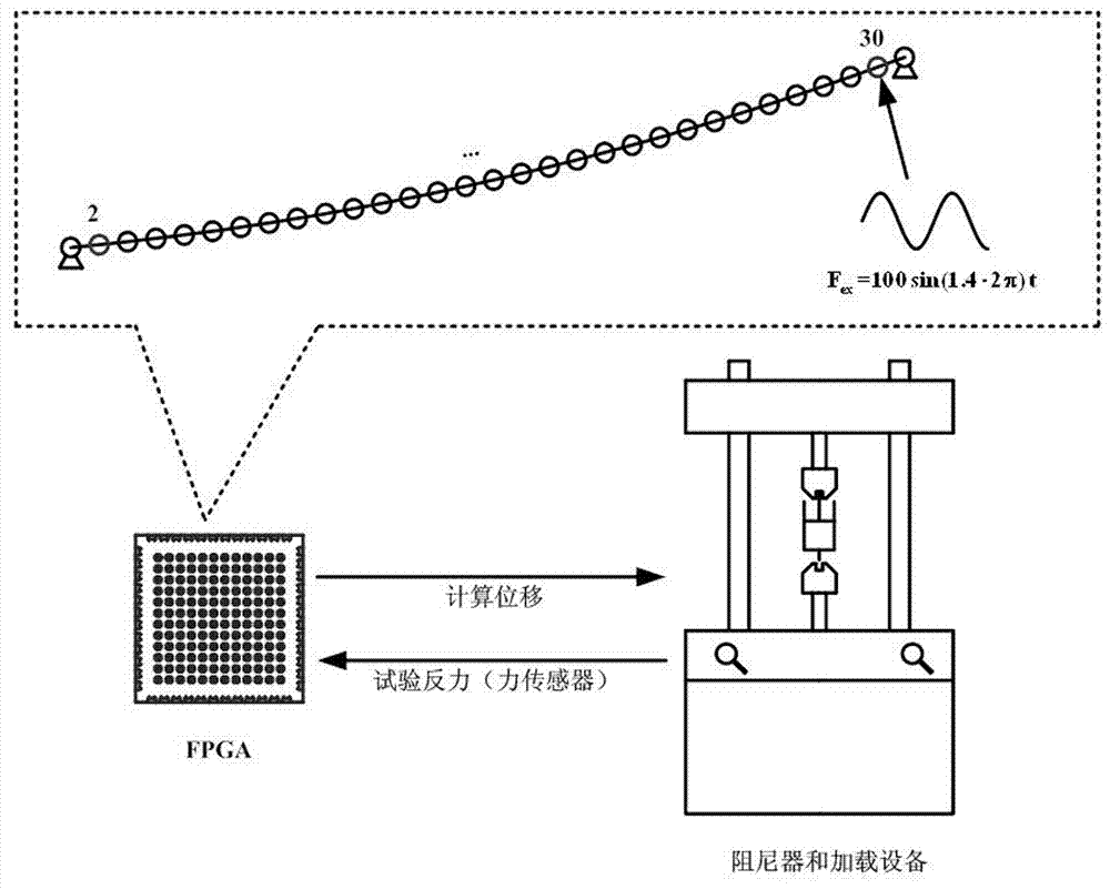
[0069] Describe the specific embodiment of the present invention in detail below in conjunction with accompanying drawing and embodiment, wherein figure 1 It is a schematic flow chart of an embodiment of the present invention. In this embodiment, a real-time substructure hybrid test based on vector finite element and FPGA is used to test the structural dynamic response of the cable-stayed damping system. The schematic diagram of the real-time substructure test of the cable-stayed damper system based on vector finite element and FPGA is shown in Fig. figure 2 As shown, the length of the stay cable is 18.75m, the inclination angle to the ground is 12.5 degrees, the tensile stiffness EA=911000N, the linear density ρ=0.76kg / m, and the initial tension is 1286N. As a simple example, here the damper is selected as a pure viscous damper with damping coefficient C=300N·s / m, and it is placed below the No. 2 node. The implementation steps of the real-time substructure test based on th...


PUM


Abstract

The present invention discloses a hybrid test method based on a vector finite element and an FPGA. The method comprises the following steps: dividing a to-be-analyzed structure into a numerical sub-structure and an experimental sub-structure; establishing a numerical model in an FPGA by using a parallel computing technology and adopting a vector finite element; writing an external compensation controller in the FPGA by using a control theory of feed-forward plus feedback; designing I / O in the FPGA to implement conversion and transfer between a numerical computation amount and an experimental simulation amount; running an FPGA hardware program regularly by using a LabVIEW real-time module; transferring data between FPGA hardware and a host computer by using FIFO; setting up a displacement loading device of the experimental sub-structure and establishing a connection with an I / O module of the FPGA hardware; and in the host computer, establishing a data communication interface between the host computer and an FPGA hardware terminal, so as to realize visualization of experimental data. The method provided by the present invention can effectively solve the problem of excessive computing pressure caused by numerical sub-structure calculation in a hybrid experiment, and is particularly suitable for a hybrid experiment in which a numerical sub-structure has a large number of computing degrees of freedom and requires real-time operation.

Description

technical field [0001] The invention relates to the technical field of civil engineering test, in particular to a hybrid test method based on vector finite element and FPGA. Background technique [0002] Hybrid test is a new test method developed in recent years for testing the dynamic response of large civil structures under extreme environmental loads, such as earthquakes, typhoons, floods, etc. The hybrid test divides civil structural members into numerical substructures that are easy to simulate under the linear elastic stress state and experimental substructures that involve nonlinear and elastoplastic mechanical behaviors and are difficult to calculate according to the complexity of mechanical properties. The combined method obtains the dynamic response of the numerical value and experimental substructure respectively, and realizes the dynamic performance analysis of the whole structure through the data transfer at the boundary of the substructure. The hybrid test is ...

Claims


Application Information

Patent Timeline
Patent Type & Authority Applications(China)
IPC IPC(8): G06F17/50
CPCG06F30/23
Inventor 段元锋陶俊杰章红梅
Owner ZHEJIANG UNIV
Why Eureka
Try Eureka