Ultrasonic cleaner

An ultrasonic cleaner technology, applied in the field of ultrasonic cleaners, can solve the problems of steel wire surface corrosion resistance decline, steel wire surface gap corrosion, large workshop area, etc., and achieve the effects of low cost, increased strength and high utilization rate

Active Publication Date: 2017-12-15
湖州永兴特种不锈钢有限公司
View PDF9 Cites 1 Cited by
  • Summary
  • Abstract
  • Description
  • Claims
  • Application Information

AI Technical Summary

Problems solved by technology

[0002] There are a large number of gullies on the surface of the existing steel wire, and the black substance in the gully is wire drawing powder. When the weather is wet, a layer of water film is formed on the surface of the steel wire, and the wire drawing powder electrochemically corrodes with the steel wire in the aqueous solution. Crevice corrosion occurs on the surface of the steel wire, and these factors cause the corrosion resistance of the steel wire surface to decline
[0003] At present, the way to deal with this situation is generally to use ultrasonic cleaning. The existing ultrasonic cleaners have a single function, either they can only clean the steel wires in the feed, or they are only used for cleaning steel wire products (such as springs). Ultrasonic cleaning of steel wire or steel wire products that cannot be conveyed requires two sets of completely different ultrasonic cleaners, which are costly, require a lot of equipment, and occupy a large area of ​​the workshop

Method used


Image

  • Ultrasonic cleaner
  • Ultrasonic cleaner
  • Ultrasonic cleaner

Examples


Embodiment 1

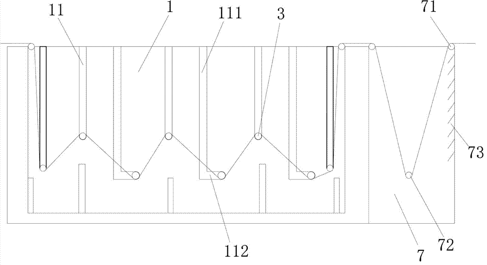
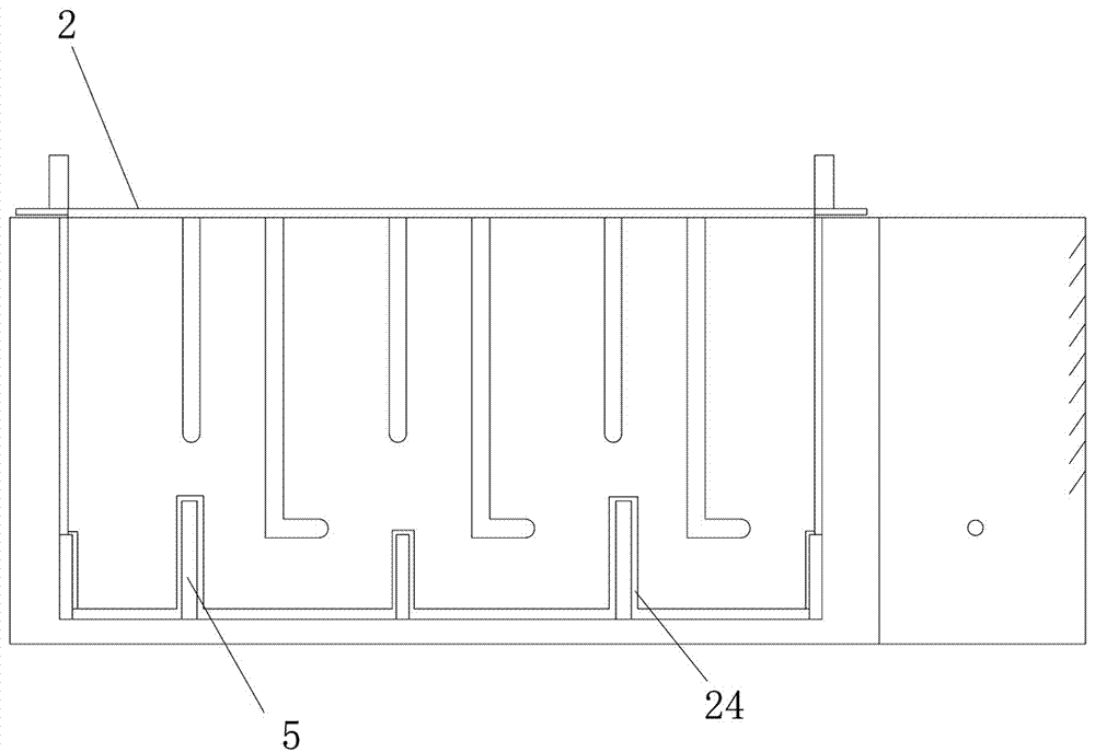
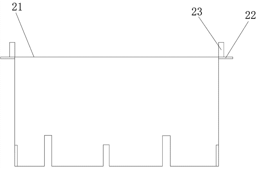
[0035] An ultrasonic cleaner, the ultrasonic cleaner includes a cleaning tank 1 with ultrasonic vibration, a filter screen frame 2 that can be erected in the cleaning tank, and a number of transfer rollers 3 that can be arranged in the cleaning tank; The filter screen frame includes a frame body 21 and a frame 22 located on the outer edge of the top of the frame body, and a hoisting ring 23 is arranged on the frame body.

[0036] A group of opposite tank walls on both sides of the cleaning tank are correspondingly provided with several roller slots 11 for cooperating with the two ends of the conveying rollers. It includes an introduction groove 111 that extends upwards to the top of the cleaning tank and is open at the upper end to form an insertion port. At least part of the roller insertion groove also includes a locking groove 112 that communicates with the bottom of the introduction groove and forms a knuckle with the introduction groove. .

[0037] The roller fitting gro...

Embodiment 2

[0041] The difference from the above embodiment is that every two adjacent conveying rollers form a group, and the two ends of the two conveying rollers are connected with connecting rods 4 . The conveying rollers of the above structure are set in pairs, and each group is set up and down. The steel wire reciprocates up and down in the washer, which lengthens the distance in the washer and improves the cleaning efficiency. It will not run up, so only one introduction groove is needed. The introduction groove is a long groove, and the transmission roller is not easy to fall out and easy to install. The locking groove of the lower groove can hold the transmission roller in this position and not along the introduction The groove runs upwards and escapes from the groove, and the conveying roller is also driven to press into the locking groove during the traveling process of the steel wire.

[0042] The connecting rod includes a rod body 41 and a collar 42 fixed at both ends of the ...

Embodiment 3

[0045] The difference from the above-mentioned embodiment is that the wall of the cleaning tank is provided with several frame bars 5 that protrude into the tank, and the filter screen frame is provided with a frame bar that is formed by the filter screen indenting into the frame. The shelf groove 24 that bridge connects.

[0046] The setting of the frame makes the cleaning tank fully drive the vibration of the filter screen frame, thereby realizing the follower effect, and the entire filter screen frame also undergoes ultrasonic vibration to improve the ultrasonic cleaning efficiency. And the frame bar improves the stability of the filter screen frame, and the frame groove improves the strength of the filter screen frame. The upper end of the rack tank is sealed to form a horizontal rack surface, the bottom end of the rack bar is connected to the bottom plate of the cleaning tank, and the upper end is lower than the top of the cleaning tank.

[0047] The frame bars are divid...


PUM


Abstract

The invention belongs to the field of material surface treatment, in particular to an ultrasonic cleaner. The ultrasonic cleaner comprises a cleaning tank with the ultrasonic vibration function, a filter screen frame and a plurality of conveying rollers, wherein the filter screen frame can be erected in the cleaning tank, and the conveying rollers can be arranged in the cleaning tank; the filter screen frame comprises a frame body and a framework, wherein the framework is located at the outer edge of the top of the frame body; a lifting ring is arranged on the framework; and a plurality of roller embedding grooves matched with the two ends of the conveying rollers are correspondingly formed in a group of two opposite side groove walls in the cleaning tank and are formed in the groove walls in a sunken mode. The ultrasonic cleaner has the advantage of being capable of being optionally assembled and matched with the filter screen frame or the conveying rollers according to the characteristics of steel wires or steel wire products, for example, the filter screen frame is used for cleaning the steel wire products (such as springs), the conveying rollers can be used for cleaning the steel wires in the conveying process, the filter screen frame and the conveying rollers are convenient to assemble and disassemble, and the cleaner is suitable for multiple products, wide in application range, simple in structure and low in cost.

Description

technical field [0001] The invention belongs to the field of material surface treatment, and in particular relates to an ultrasonic cleaner. Background technique [0002] There are a large number of gullies on the surface of the existing steel wire, and the black substance in the gully is wire drawing powder. When the weather is wet, a layer of water film is formed on the surface of the steel wire, and the wire drawing powder electrochemically corrodes with the steel wire in the aqueous solution. Crevice corrosion occurs on the surface of the steel wire, and these factors cause the corrosion resistance of the steel wire surface to decline. [0003] At present, the way to deal with this situation is generally to use ultrasonic cleaning. The existing ultrasonic cleaners have a single function, either they can only clean the steel wires in the feed, or they are only used for cleaning steel wire products (such as springs). Ultrasonic cleaning of steel wire or steel wire product...

Claims


Application Information

Patent Timeline
Patent Type & Authority Applications(China)
IPC IPC(8): B08B3/12B08B3/14
CPCB08B3/123B08B3/14
Inventor 史茜陈根保米振莉高亦斌杨雪澜杨国华丁晓波耿俊华
Owner 湖州永兴特种不锈钢有限公司
Why Eureka
Try Eureka