
Broaching tool structure

A tie rod and blade face technology, which is applied to broaches, broaching machines, accessories of broaching machines, etc., can solve the problems of difficult processing, changes in shaft rotation accuracy, consistency, poor stability, etc., to reduce production costs and The effect of maintenance cost, improving matching accuracy and ensuring stability

Active Publication Date: 2017-12-15
GUANGZHOU HAOZHI ELECTROMECHANICAL
View PDF5 Cites 0 Cited by
  • Summary
  • Abstract
  • Description
  • Claims
  • Application Information

AI Technical Summary

Problems solved by technology

[0004] (1) The processing is difficult and the cost of repeated maintenance is high. Due to the need for multiple parts to cooperate, the accuracy of the corresponding positions of multiple parts must be guaranteed at the same time. Make sure to tighten the handle;
[0005] (2) Consistency and stability are poor. Since the movement of multiple mating parts is restricted by dimensional positioning, only by improving the accuracy of the parts can repeat positioning accuracy and interchangeability be ensured, and because the parts cannot ensure the parts after each loose broach Shafting performance is not guaranteed as position does not change
[0006] (3) The broach mechanism is a rotating part inside the main shaft or the machine tool. When there is inconsistency before and after loosening the broach, the rotation accuracy of the shaft system will change, which will affect the life of the parts and the processing accuracy of the equipment. There is a risk of damage to the equipment when the vibration is too large

Method used


Image

  • Broaching tool structure
  • Broaching tool structure
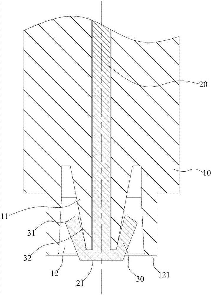
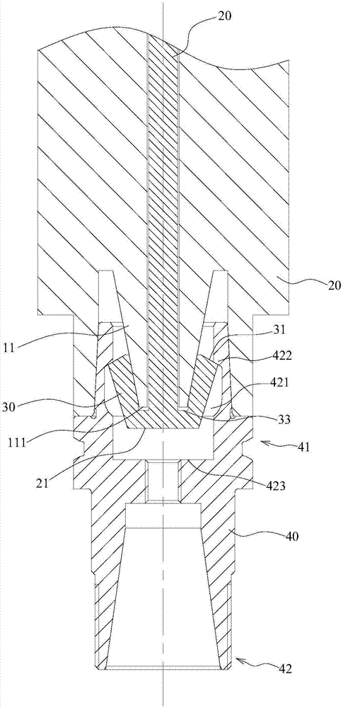
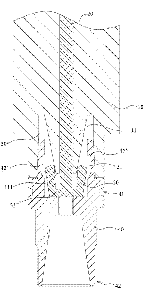
  • Broaching tool structure

Examples


Embodiment Construction

[0024] Below, the present invention will be further described in conjunction with the accompanying drawings and specific implementation methods. It should be noted that, under the premise of not conflicting, the various embodiments described below or the technical features can be combined arbitrarily to form new embodiments. .

[0025] Such as Figure 1-3 As shown, the present invention provides a broach structure, aiming at the assembly relationship between the HSK numerical control tool handle and the shaft system 10, compared with the existing broach structure, the stability and consistency are higher, and the loose broach alignment is reduced. Influenced by the accuracy of the system 10, the broach structure includes a shaft system 10 and a broach assembly; the broach assembly is coaxially arranged with the shaft system 10 and rotates synchronously with the shaft system 10, and the broach assembly includes a pull rod 20 and a pull claw 30; the pull rod 20 Pass through the...


PUM


Abstract

The invention discloses a broaching tool structure, and belongs to the field of numerical control machine tool clamps. The structure comprises a shaft system and a broaching tool assembly; the broaching tool assembly and the shaft system are coaxially arranged, and synchronously rotate, the broaching tool assembly comprises a pull rod and a pull pawl, the pull rod penetrates the shaft system along the central axis of the shaft system and extends out of the shaft system, the stretching end is fixedly connected with the pull pawl, the pull rod can do reciprocated movement along the central axis of the shaft system so as to drive the pull pawl to extend out of the shaft system or abut against the shaft system, the pull pawl has elastic stress shrinking towards the pull rod, the shaft system is provided with a broaching tool guide block which is arranged in the circumferential direction of the pull rod and used for supporting the pull pawl open in the direction away from the shaft system, and structural stability is ensured; due to the fact that compared with an existing broaching tool structure, the broaching tool structure is few in adopted part, size fit between the parts easily meets consistency, the influence of the broaching tool loosening on the precision of the shaft system is reduced, and production cost and maintaining cost are reduced.

Description

technical field [0001] The invention relates to a fixture of a numerical control machine tool, in particular to a broach structure. Background technique [0002] At present, the shafting or machine tools using HSK tool holders mainly use top cores, pull claws, and sliding cores to tighten the tool holders. [0003] However, the existing broach structure for the HSK handle has the following defects: [0004] (1) The processing is difficult and the cost of repeated maintenance is high. Due to the need for multiple parts to cooperate, the accuracy of the corresponding positions of multiple parts must be guaranteed at the same time. Make sure to tighten the handle; [0005] (2) Consistency and stability are poor. Since the movement of multiple mating parts is limited by dimensional positioning, only by improving the accuracy of the parts can the repeat positioning accuracy and interchangeability be ensured, and because the parts cannot ensure the parts after each loose broach ...

Claims


Application Information

Patent Timeline
Patent Type & Authority Applications(China)
IPC IPC(8): B23D43/02B23D39/00B23Q3/155
CPCB23D39/00B23D43/02B23Q3/155
Inventor 单杰汤秀清
Owner GUANGZHOU HAOZHI ELECTROMECHANICAL
Learn More