Automatic paving method and device of fiber cloth for wind power blade main beam molding

A technology of wind power blades and fiber cloth, which is applied in the field of automatic laying of fiber cloth for forming the main beam of wind power blades

Active Publication Date: 2017-12-15
SHANDONG UNIV OF TECH
View PDF9 Cites 11 Cited by
  • Summary
  • Abstract
  • Description
  • Claims
  • Application Information

AI Technical Summary

Problems solved by technology

[0003] The purpose of the present invention is to propose a mechanized autom...

Method used


Image

  • Automatic paving method and device of fiber cloth for wind power blade main beam molding
  • Automatic paving method and device of fiber cloth for wind power blade main beam molding
  • Automatic paving method and device of fiber cloth for wind power blade main beam molding

Examples


Embodiment Construction

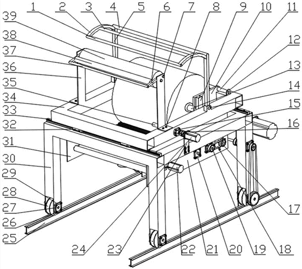
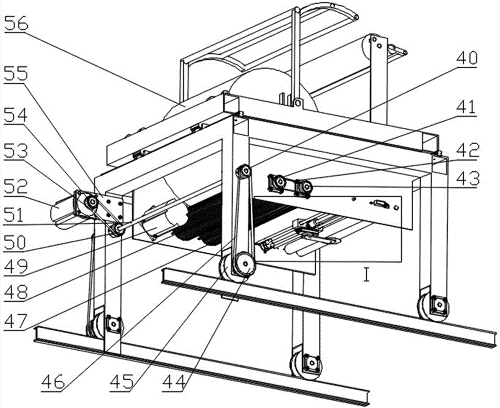
[0011] 1. Fabric frame beam Ⅰ 2. Fabric frame connecting frame Ⅱ 3. Fabric frame beam Ⅱ 4. Fabric frame beam Ⅲ 5. Fabric frame connecting frame Ⅰ 6. Rubber roller connecting frame 7. Pin Ⅰ 8, screw Ⅰ 9, chute 10. Baffle plate 11, baffle plate fixed shaft 12, fixed support 13, cloth roll fixed mandrel 14, pin II 15, screw nut I 16, coupling I 17, synchronous pulley II 18, synchronous belt I 19 , synchronous pulley Ⅰ 20, bearing seat Ⅰ 21, lower support plate Ⅱ 22, cloth cutting motor 23, adjustment motor support plate 24, adjustment motor 25, guide rail 26, screw Ⅱ 27, travel shaft 28, travel wheel Ⅱ 29, bearing Seat II 30, lower frame 31, lower support plate I 32, slider 33, guide rail 34, upper frame 35, lead screw 36, rubber roller support plate 37, operating beam 38, small rubber roller 39, large rubber roller 40, Timing pulley Ⅶ 41, timing pulley Ⅲ 42, timing belt Ⅱ 43, timing pulley Ⅳ 44, timing pulley Ⅷ 45, walking wheel Ⅰ 46, timing belt Ⅳ 47, cloth feeding rubber wheel...


PUM


Abstract

The invention provides automatic layer paving equipment of fiber cloth for a wind power blade main beam. The equipment comprises a main car and a cloth clamping positioning device. The main car comprises an upper frame, a lower frame, a cloth rack, a guide rubber roller mechanism, a cloth roll positioning mechanism, a cloth feeding mechanism, an upper frame left-right adjustment mechanism, a main car walking mechanism and a cloth cutting mechanism; the cloth clamping positioning device comprises a walking mechanism and a cloth clamping mechanism; the cloth clamping positioning device clamps cloth at one end; the main car drives a cloth roller to reach consistency with the advancement speed of the main car through a cloth feeding rubber roller I and a cloth feeding rubber roller II to guarantee constant tension of the fiber cloth in the paving process; the cloth paving length precision is guaranteed through transmission modes of servo motor driving and a synchronous belt; and the fiber cloth clamping stability is guaranteed through lead screw driven staggered-tooth clamping jaws in the cloth clamping positioning device. The equipment replaces manual fiber cloth paving work, is high in mechanical cloth paving efficiency, is simple in structure and liable to operate, and greatly reduces the cloth paving cost of wind power blades.

Description

technical field [0001] The invention relates to a fiber cloth laying technology for a main girder of a wind power blade, in particular to a fiber cloth automatic laying method and device for forming a main girder of a wind power blade. Background technique [0002] At present, the laying of the main girder fiber cloth of wind power blades is mainly done manually. To complete the laying of a girder fiber cloth requires two skilled workers to walk about 6 kilometers back and forth, which takes about 2 hours. In order to improve the working environment and labor intensity of workers on the premise of ensuring accuracy, according to on-site observation and discussion and analysis, it is proposed to simulate the manual operation process and replace manual labor with electromechanical equipment to reduce labor intensity, improve labor efficiency, and stabilize product quality. A method and device for automatic laying of fiber cloth for forming the main girder of wind power blades ...

Claims


Application Information

Patent Timeline
IPC IPC(8): B65H47/00B65H20/16B65H20/04B65H23/26B65H35/08
CPCB65H20/04B65H20/16B65H23/26B65H35/08B65H47/00B65H2301/122B65H2701/174B65H2701/1842
Inventor 张磊安刘卫生黄雪梅袁光明黄辉秀袁伟文永双于祥勇
Owner SHANDONG UNIV OF TECH
Why Eureka
Try Eureka