Visible current power line

A power line and current technology, applied in the direction of circuits, insulated cables, electrical components, etc., can solve the problems of easy contact with other wires, affect the effect of electrical connection, and poor insulation effect, so as to avoid unstable quality and chasing light Good effect, excellent insulation effect

Inactive Publication Date: 2013-03-06
蔡祥轩
View PDF6 Cites 5 Cited by
  • Summary
  • Abstract
  • Description
  • Claims
  • Application Information

AI Technical Summary

Problems solved by technology

[0003] The patent No. 200510019319.X, the application date is August 19, 2005, and the authorized announcement date is January 19, 2011. The invention patent "electroluminescent cable that emits light sequentially segment by segment" discloses a visible current power cord , the insulating medium on the metal base line is a mixture of titanium dioxide and polyurethane, which has poor viscosity and poor insulation effect. It is not aesthetically pleasing when used for charging lines of trendy electronic devices such as ihone4, HTC, and Samsung mobile phones; the metal base line is a wire diameter of 0.03—0.20 mm round wire, due to the small wire diameter, the power cord is soft, not strong enough, and the life is very low; there are two auxiliary electrodes wrapped around the luminous core wire, which requires high processing costs to realize the auxiliary electrode outside the luminous core wire The winding of the outermost transparent plastic layer of the power cord is completely exposed when the outermost transparent plastic layer is peeled and soldered, and it is easy to contact with other wires, and the quality is unstable, which affects the effect of electrical connection

Method used


Image

  • Visible current power line
  • Visible current power line

Examples


Embodiment Construction

[0015] The present invention will be described in further detail below in conjunction with the accompanying drawings and embodiments.

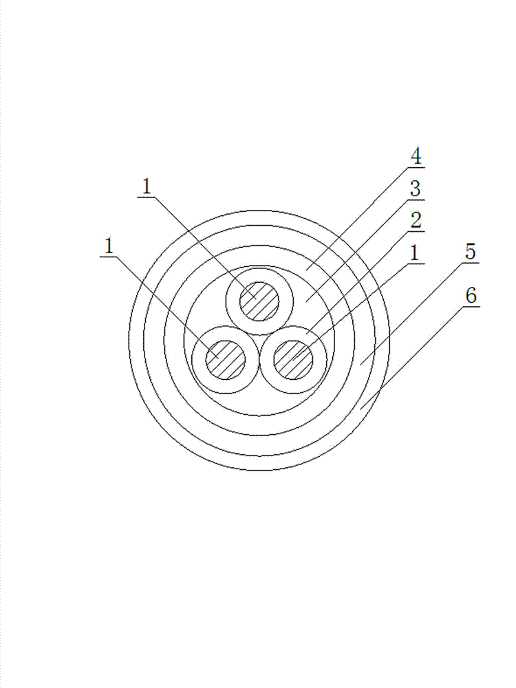
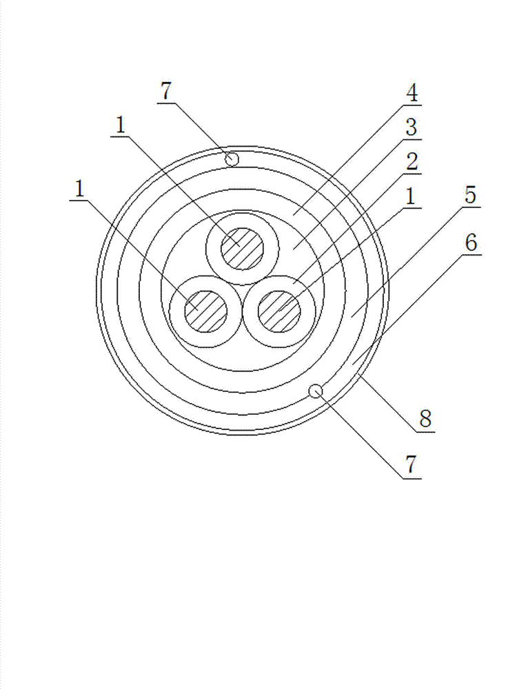
[0016] Figure 1, figure 2 As shown, the present invention discloses a visible current power supply line, which includes one or more flexible central electrodes 1, and a light-emitting layer 4 and a light-transmitting conductive layer 5 that are sequentially sleeved outside the central electrodes 1. Each of the described The outer wall of the central electrode 1 is covered with an insulating layer 2, the insulating layer 2 is a polyurethane coating containing polyisocyanate, the central electrode 1 is a round wire with an outer diameter of 0.205-0.25 mm, one or more central electrodes 1 The outside is coated with an insulating sheath 3, the luminous layer 4 is arranged outside the insulating sheath 3, and the transparent plastic layer 5 is also provided with a transparent plastic layer 6, and characters or patterns are printed on the transpar...


PUM


Abstract

The invention discloses a visible current power line, comprising one or a plurality of flexible central electrodes, a light-emitting layer and a light-transmitting conductive layer, wherein the light-emitting layer and the light-transmitting conductive layer are sequentially sleeved outside the central electrodes; an insulating layer is coated on the outer wall of each central electrode; the insulating layer is a polyurethane coating containing polyisocyanate; each central electrode is a circular line with the outer diameter of 0.205-0.25 mm; an insulating sleeve layer is sleeved outside one or a plurality of the flexible central electrodes; the light-emitting layer is arranged outside the insulating sleeve layer; a transparent plastic layer is further arranged outside the light-transmitting conductive layer; a color-changing plastic layer is arranged outside the transparent plastic layer; and light-emitting powder grains in the light-emitting layer are covered by transparent, insulating and dielectric thermoplastic high-molecular polymer. The power line disclosed by the invention has the advantages of good insulating effect, long service life, low machining cost, stable and reliable quality and large light-emitting area, and can be widely applied to fields of analogy, decoration, advertisements, technical knitting and the like.

Description

technical field [0001] The invention belongs to cable products, in particular to a power cord for luminous display. Background technique [0002] The appearance of various existing power cords cannot show whether they are powered on or working. question. The luminous core wire is coated with an insulating medium layer, a luminescent powder layer and a transparent conductive layer on the outer wall of a metal base line in sequence. Such a luminous core wire will emit light when it is powered on, so it can show the working status and make the ordinary power line more attractive. new features and dynamics. [0003] The patent No. 200510019319.X, the application date is August 19, 2005, and the authorized announcement date is January 19, 2011. The invention patent "electroluminescent cable that emits light sequentially segment by segment" discloses a visible current power cord , the insulating medium on the metal base line is a mixture of titanium dioxide and polyurethane, wh...

Claims


Application Information

Patent Timeline
Patent Type & Authority Applications(China)
IPC IPC(8): H01B7/00H01B7/02H01B7/17H01B7/36
Inventor 蔡祥轩
Owner 蔡祥轩
Why Eureka
Try Eureka