
Vehicle-mounted movable multifunctional weight hoisting equipment

A kind of hoisting equipment and multi-functional technology, applied in hoisting device, clockwork mechanism, etc., can solve the problems of affecting the efficiency of transportation, high labor intensity of workers, and large occupation, so as to facilitate installation and disassembly and reduce labor intensity of workers , easy to manufacture effects

Pending Publication Date: 2017-12-15
HUANGHE S & T COLLEGE
View PDF6 Cites 1 Cited by
  • Summary
  • Abstract
  • Description
  • Claims
  • Application Information

AI Technical Summary

Problems solved by technology

At present, heavy construction materials or equipment are generally hoisted by large cranes, and smaller and lighter construction materials or equipment are manually operated. Due to the high cost of using large cranes and the slow transition speed, it affects transportation. The efficiency, the labor intensity of the workers is high, which also affects the construction efficiency
In addition, the existing cranes only play the role of hoisting heavy objects. Since cutting machines are often used to cut materials on the construction site, and grinding wheels are often used to polish tools, more equipment is required, which not only takes up a lot of space , and not easy to maintain and manage

Method used


Image

  • Vehicle-mounted movable multifunctional weight hoisting equipment
  • Vehicle-mounted movable multifunctional weight hoisting equipment
  • Vehicle-mounted movable multifunctional weight hoisting equipment

Examples


Embodiment Construction

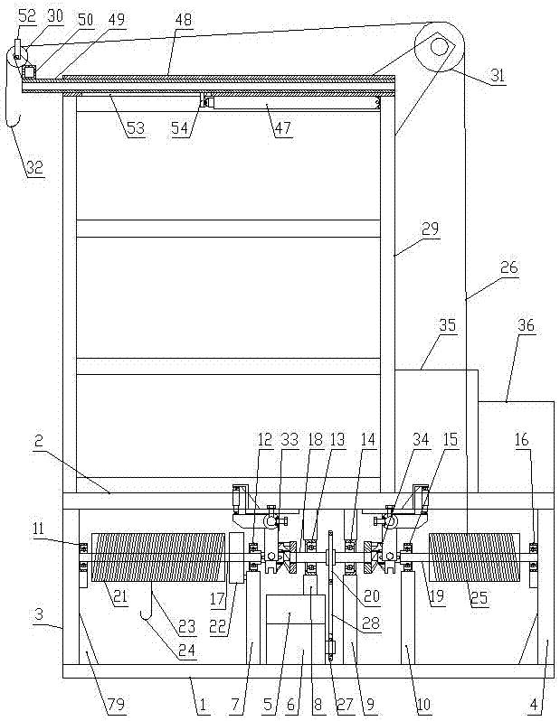
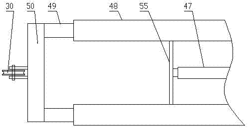
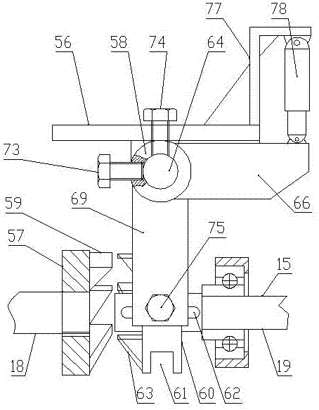
[0035] Such as Figure 1-Figure 7 As shown, the present invention comprises a lower frame 1 and an upper frame 2 arranged horizontally, the left side and the right side between the lower frame 1 and the upper frame 2 are respectively fixedly provided with a left frame 3 and a right frame 4, and the lower frame 1 A drive motor 5 and a gearbox 6 are provided, and the upper surface of the lower frame 1 is provided with a first support frame 7, a second support frame 8, a third support frame 9 and The fourth support frame 10, wherein the top of the second support frame 8 and the third support frame 9 are fixedly connected with the lower surface of the upper frame 2, the left frame 3 right side is provided with a first bearing seat 11, and the first support frame 7 is provided with The second bearing seat 12, the second support frame 8 is provided with the third bearing seat 13, the third support frame 9 is provided with the fourth bearing seat 14, the fourth support frame 10 is pr...


PUM


Abstract

Vehicle-mounted movable multifunctional weight hosting equipment comprises a left driving shaft, a main driving shaft and a right driving shaft, wherein the left driving shaft, the main driving shaft and the right driving shaft are arranged from left to right in sequence and located on the same center line. A cutting disc and a grinding wheel are coaxially and fixedly arranged on the left driving shaft. A hoisting roller is coaxially and fixedly arranged on the right driving shaft, and a hoisting rope is wound on the hoisting roller. A hoisting space frame is fixedly arranged on the left side of the top of an upper frame, and a telescopic hydraulic lazy arm which is horizontally telescopic in the left-right direction is arranged at the top of the hoisting space frame. Hydraulic drive type clutches are arranged between one end of the main driving shaft and the left driving shaft as well as between the other end of the main driving shaft and the right driving shaft correspondingly. According to the vehicle-mounted movable multifunctional weight hosting equipment, devices which are frequently used for building construction such as hoisting, cutting, polishing and the like are integrated, and the structure is compact; one power source is used for conversion through the clutches, the cost is reduced, and the flexibility is high; the hoisting equipment can be moved to any places of a construction field according to requirements, and thus the labor intensity of workers is relieved; and hoisting, cutting and polishing can be conducted separately, and thus maintenance and management in the later stage are facilitated.

Description

technical field [0001] The invention belongs to the technical field of hoisting, and in particular relates to a vehicle-mounted mobile multifunctional heavy object hoisting device. Background technique [0002] In civil engineering construction sites such as buildings, roads, and bridges, the transport vehicle transports construction materials or equipment for the construction site, and the transport vehicle transports the construction materials or equipment here to other construction sites. It is necessary to transport the construction materials or equipment on the transport vehicle Transport to the ground, and transport the construction materials or equipment on the ground to the transport vehicle. At present, heavy construction materials or equipment are generally hoisted by large cranes, and smaller and lighter construction materials or equipment are manually operated. Due to the high cost of using large cranes and the slow transition speed, it affects transportation. T...

Claims


Application Information

Patent Timeline
Patent Type & Authority Applications(China)
IPC IPC(8): B66D1/14B66D1/12
CPCB66D1/12B66D1/14
Inventor 马志国张萍齐俊平
Owner HUANGHE S & T COLLEGE
Learn More