Energy-saving equipment remote control device

A technology of remote control device and energy-saving equipment, applied in mechanical equipment, lighting device, lighting device and other directions, can solve the problems of inability to monitor the environment of street light poles, and inability to adjust energy-saving lamps

Active Publication Date: 2019-06-25
耀有光科技集团有限公司
View PDF7 Cites 0 Cited by
  • Summary
  • Abstract
  • Description
  • Claims
  • Application Information

AI Technical Summary

Problems solved by technology

[0004] The invention with the application number 201610529246.7 proposes an energy-saving LED street lamp control method, including initialization, adjusting the height of the LED and the distance from the light pole, obtaining the maximum wind energy corresponding angle, adjusting the angle of the wind power generation device, adjusting the angle of the solar battery group, and collecting electric energy Combined storage with wind energy, collection and processing of light intensity, power and lighting time control, parameter collection and wireless control steps, multiple functions, high energy efficiency, good heat dissipation, long service life, low maintenance costs, and energy saving and environmental protection, effectively saving energy The control is intelligent and the lighting area is wide. However, this invention cannot intuitively monitor the environment around the street light pole, and cannot intuitively adjust the energy-saving lamps through the environment around the street light pole. It has certain limitations in use.

Method used


Image

  • Energy-saving equipment remote control device
  • Energy-saving equipment remote control device
  • Energy-saving equipment remote control device

Examples


Embodiment Construction

[0021] The following will clearly and completely describe the technical solutions in the embodiments of the present invention with reference to the accompanying drawings in the embodiments of the present invention. Obviously, the described embodiments are only some, not all, embodiments of the present invention.

[0022] Example.

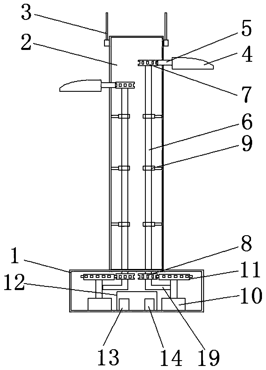
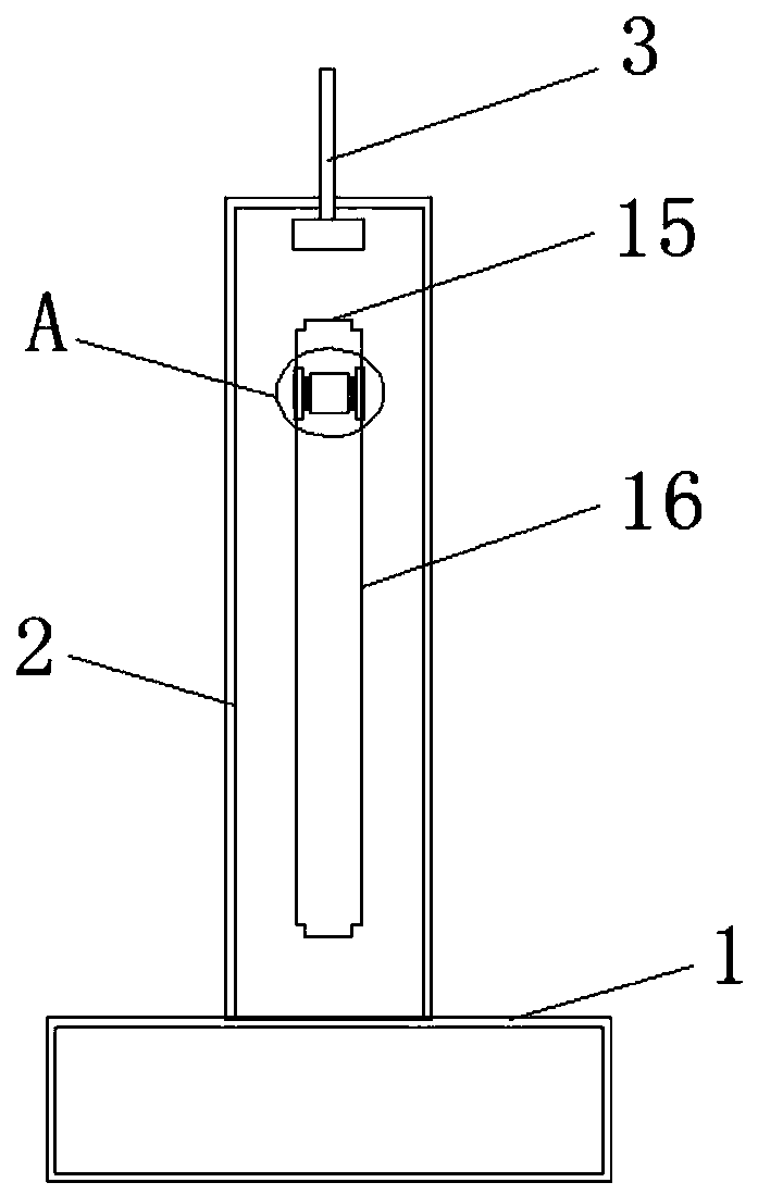
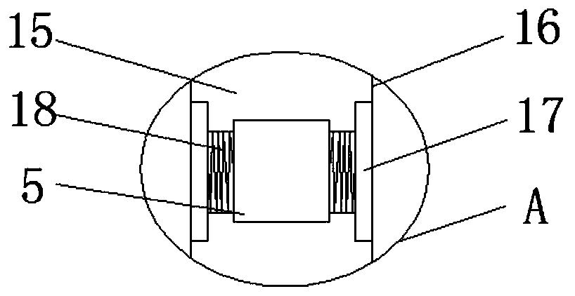
[0023] refer to Figure 1-5 , a remote control device for energy-saving equipment, including a base 1 and a light pole 2 fixedly installed on the top of the base 1. Both the base 1 and the light pole 2 are hollow structures, and the two sides of the light pole 2 are symmetrically equipped with movable blocks 5, two movable blocks 5 are fixedly installed with energy-saving lamps 4 for lighting at one end far away from each other. The movable block 5 is provided with a monitoring mechanism for monitoring the surrounding environment of the light pole 2 and the usage of the energy-saving lamps 4 . 4. A sliding mechanism that moves up and down. The base...


PUM


Abstract

The invention discloses an energy-saving equipment remote control device. The energy-saving equipment remote control device comprises a base and a lamp post fixedly installed at the top end of the base. The base and the lamp post are both of hollow structures, movable blocks are symmetrically and movably installed on the two sides of the lamp post, energy-saving lamps used for illuminating are fixedly installed at one ends, away from each other, of the two movable blocks, monitoring mechanisms used for monitoring the surrounding environment of the lamp post and the using condition of the energy-saving lamps are arranged on the movable blocks; and sliding mechanisms used for driving the energy-saving lamps to move up and down are arranged on the two sides of each movable block, position adjusting mechanisms used for adjusting the height and the angle of each energy-saving lamp are arranged in the base and the lamp post, and the position adjusting mechanisms are connected with the sliding mechanisms. According to the energy-saving equipment remote control device, the height and angle positions of the energy-saving lamps can be adjusted remotely through data detected by a camera, the energy-saving equipment remote control device is suitable for the using requirements of various environments, the effects of high efficiency and energy conservation are achieved, the structure is simple, and using is convenient.

Description

technical field [0001] The invention relates to the technical field of energy-saving equipment, in particular to a remote control device for energy-saving equipment. Background technique [0002] With the rapid growth of the world economy, the global energy shortage is becoming more and more serious, and the calls for energy conservation and emission reduction and the search for a low-carbon development model are getting louder and louder. Under this background, the development of the energy-saving lamp industry is in full swing, especially the application of energy-saving lamp light source modularization has attracted much attention. [0003] Policies and regulations are used to support the development of renewable energy. With the continuous acceleration of urban and new rural construction, wind-solar hybrid new energy energy-saving street lamps have been widely promoted and applied in China. [0004] The invention with the application number 201610529246.7 proposes an en...

Claims


Application Information

Patent Timeline
Patent Type & Authority Patents(China)
IPC IPC(8): F21V21/14F21V21/34F21V21/36F21V23/04F21V33/00H04N7/18F16M11/18F16M11/10
CPCF16M11/10F16M11/18F21V21/14F21V21/34F21V21/36F21V23/04F21V33/0052H04N7/18
Inventor 熊敏梁辉定罗厚镇
Owner 耀有光科技集团有限公司
Why Eureka
Try Eureka