Composite annual cooling system capable of converting working modes

A cooling system and conversion work technology, applied in air conditioning systems, refrigerators, heating methods, etc., can solve problems such as low energy efficiency ratio and weak power

Pending Publication Date: 2017-12-15
BEIJING UNIV OF TECH
View PDF8 Cites 1 Cited by
  • Summary
  • Abstract
  • Description
  • Claims
  • Application Information

AI Technical Summary

Problems solved by technology

The characteristics of the separated heat pipe are: the working medium is circulated by thermal pressure effect, no additional power is required, and the energy efficiency ratio is high, but the power of the working medium circulation is weak, which is suitable for use under the condition of small load or large working temperature difference; the pump The characteristic of driving the heat pipe is: the working fluid is forced to circulate by the pump, and the flowing power is strong, but it needs extra power, and the energy efficiency ratio is slightly lower. It is suitable for use under the condition of large load or small temperature difference.

Method used


Image

  • Composite annual cooling system capable of converting working modes
  • Composite annual cooling system capable of converting working modes
  • Composite annual cooling system capable of converting working modes

Examples


Embodiment 1

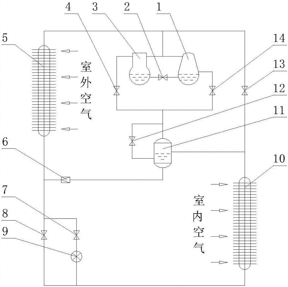
[0023] refer to figure 1 , this embodiment is a year-round cooling cooling system that can realize the conversion of three working modes: separated heat pipe, air pump driven heat pipe and mechanical refrigeration. The system consists of air pump 1, oil balance pipe 2 with control valve, compressor 3, and switching valve a4 , outdoor heat exchanger 5, one-way valve 6, switching valve b7, switching valve c8, throttling element 9, indoor heat exchanger 10, gas-liquid separator 11 with oil return port and liquid return port, with control valve Oil return pipe 12, switching valve d13, switching valve e14 and so on.

[0024] The connection relationship of the year-round cooling system is as follows: the outdoor heat exchanger 5, the switching valve 8, the indoor heat exchanger 10 and the switching valve d13 are sequentially connected into a circuit through pipelines; On the pipeline between the outdoor heat exchanger 5 and the switching valve d13, the oil balance pipe 2 with a con...

Embodiment 2

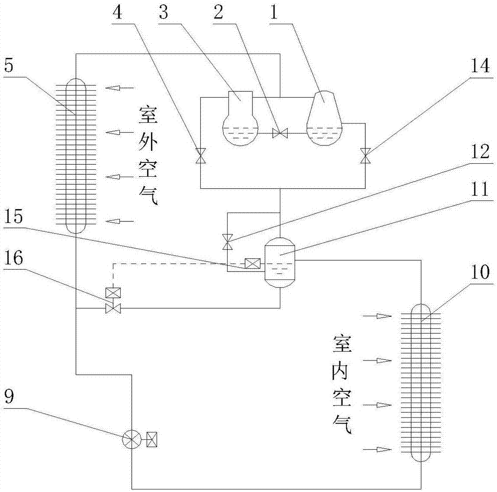
[0026] refer to figure 2 , this embodiment is an air pump-driven heat pipe compound mechanical refrigeration year-round cooling cooling system, compared with Embodiment 1, this system saves the connection from the air pump 1 and compressor 3 exhaust pipes to the inlet of the gas-liquid separator 11 The branch where the switching valve d13 at the access point is located, the switching valve b7, and the branch where the switching valve d13 is in parallel with the branch where the throttling element 9 is located. The throttling element 9 is an electric expansion valve. The one-way valve 6 is replaced by a liquid level control valve 16, and the liquid level control valve 16 is controlled by the liquid level controller 15 sensing the height of the liquid level. When the conversion valve a4 is closed and the conversion valve e14 is opened, the cooling system works in the air pump driven heat pipe mode; when the conversion valve e14 is closed and the conversion valve a4 is opened, ...

Embodiment 3

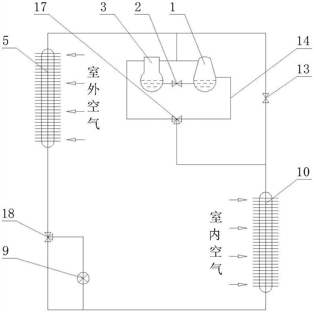
[0028] refer to image 3 , this embodiment is a year-round cooling cooling system with three working modes without a gas-liquid separator. The main difference from Embodiment 1 is: the gas-liquid separator 11 is omitted, and the air pump 1 and the compressor 3 suction pipes are now Directly connected to the pipeline between the indoor heat exchanger 10 and the switching valve d13; switching valve a4 and switching valve e14, switching valve b7 and switching valve c8 are replaced by three-way valve a17 and three-way valve b18 respectively. The system configuration and working mode conversion of other parts are the same as those in the first embodiment.


PUM


Abstract

The invention discloses a composite annual cooling system capable of converting working modes. The system comprises an air pump, an oil balance pipe with a control valve, a compressor, a conversion valve a, an outdoor heat exchanger, a one-way valve, a conversion valve b, a conversion valve c, a throttling element, an indoor heat exchanger, a gas-liquid separator, an oil return pipe with a control valve, a conversion valve d and a conversion valve e, wherein after the indoor heat exchanger absorbs heat in a machine room or a machine cabinet, a liquid working medium in the indoor heat exchanger vaporizes; the vaporized working medium is conveyed to the outdoor heat exchanger through a gas pipeline, the air pump or the compressor; the working medium dissipates heat in the outdoor heat exchanger to ambient air and then enables the air to re-condense to be in a liquid state; and the working medium then flows back to the indoor heat exchanger through a liquid pipeline. The process is repeated and circulated so that the heat in the machine room or the machine cabinet is dissipated to the atmosphere under the condition that the machine room or the machine cabinet is isolated from the outside. According to the composite annual cooling system capable of converting the working modes, by adopting the device, the heat dissipation problem of the machine room or the machine cabinet is effectively solved, the size and the cost of equipment are reduced, and the energy efficiency level and reliability of operation are remarkably improved.

Description

technical field [0001] The invention mainly relates to the field of cooling technology for year-round cooling, in particular to a composite year-round cooling system with switchable working modes, which belongs to the field of cooling technology. Background technique [0002] Data room or cabinet, power transmission substation and other places where equipment is placed or inside the equipment, the cooling system is required throughout the year to dissipate the heat generated by the equipment or components to the atmosphere to maintain the ambient temperature in the equipment room or cabinet to ensure the normal operation of the equipment run. In order to achieve the purpose of energy saving and emission reduction, the main method is: use mechanical refrigeration to cool down the machine room or cabinet in high temperature season, and use heat pipe high-efficiency heat exchange technology for natural cooling to cool down in low temperature season. At present, the heat pipe n...

Claims


Application Information

Patent Timeline
Patent Type & Authority Applications(China)
IPC IPC(8): F24F5/00F25B41/00F25B41/40
CPCF24F5/001F25B41/40
Inventor 马国远魏川铖周峰李富平
Owner BEIJING UNIV OF TECH
Why Eureka
Try Eureka