
Charging control method and system

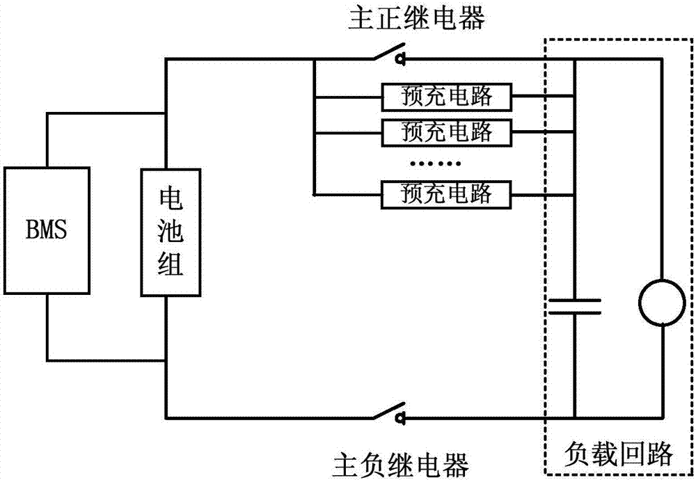
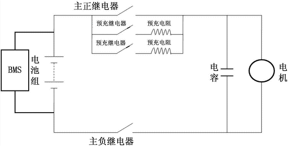
A charging control method and pre-charging technology, which are applied in the direction of secondary battery charging/discharging, current collectors, electric vehicles, etc., and can solve the problems that the pre-charging process cannot be carried out normally, affect the normal use of electric vehicles, and the pre-charging circuit is damaged.

Active Publication Date: 2017-12-15
BORGWARD AUTOMOTIVE CHINA CO LTD
View PDF3 Cites 20 Cited by
  • Summary
  • Abstract
  • Description
  • Claims
  • Application Information

AI Technical Summary

Problems solved by technology

[0005] In practical applications, damage to the pre-charging circuit often occurs, resulting in the failure of the pre-charging process. For example, the large capacitor of the motor controller cannot be pre-charged, and the abnormal situation in the pre-charging process cannot be found in time in the prior art. As a result, the large capacitor of the motor controller cannot be pre-charged normally, which affects the normal use of the electric vehicle and has a negative impact on the reliability and cost of the electric vehicle

Method used


Image

  • Charging control method and system
  • Charging control method and system
  • Charging control method and system

Examples


Embodiment Construction

[0056] Various exemplary embodiments of the present invention will now be described in detail with reference to the accompanying drawings. It should be noted that the relative arrangements of components and steps, numerical expressions and numerical values ​​set forth in these embodiments do not limit the scope of the present invention unless specifically stated otherwise.

[0057] At the same time, it should be understood that, for the convenience of description, the sizes of the various parts shown in the drawings are not drawn according to the actual proportional relationship.

[0058] The following description of at least one exemplary embodiment is merely illustrative in nature and in no way taken as limiting the invention, its application or uses.

[0059] Techniques, methods and devices known to those of ordinary skill in the relevant art may not be discussed in detail, but where appropriate, such techniques, methods and devices should be considered part of the descript...


PUM


Abstract

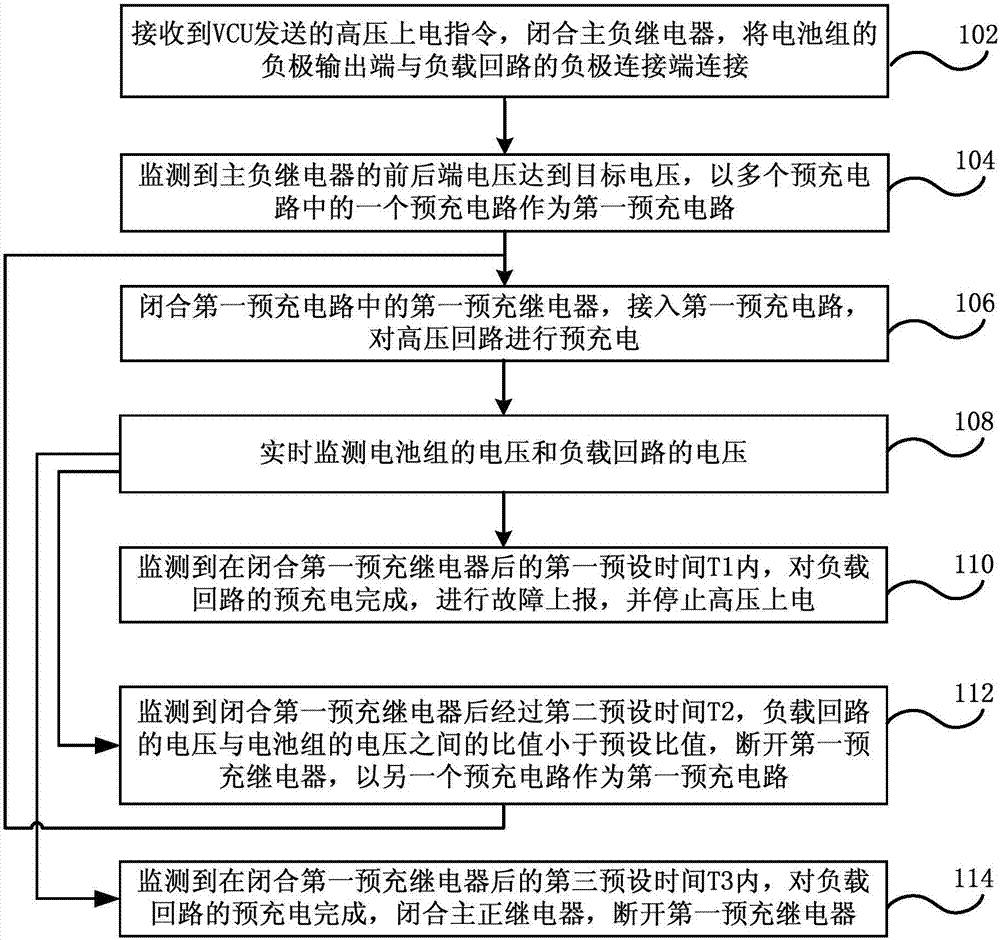
The embodiment of the present invention discloses a charging control method and system. The method includes a step of receiving a high-voltage power-on instruction sent by a VCU, closing a main negative relay, and connecting a negative output end of a battery pack to a negative connecting end of a load circuit, a step of closing a first pre-charge relay in a first pre-charge circuit when a condition that the front and back voltage of the main negative relay reaches target voltage is monitored, accessing the first pre-charge circuit and carrying out pre-charge on a high voltage loop, a step of carrying out fault reporting when the pre-charge of a load loop is completed in T1 after closing the first pre-charge relay is monitored and stopping high-voltage power-on, and a step of disconnecting the first pre-charge relay when a condition that a ratio of the voltage of the load loop to the voltage of the battery pack is smaller than a preset ratio in T2 after closing the first pre-charge relay, accessing the second pre-charge circuit, and repeating the above flow. According to the embodiment of the present invention, an abnormal condition in a pre-charge process can be timely diagnosed.

Description

technical field [0001] The invention relates to charging technology, in particular to a charging control method and system. Background technique [0002] Electric vehicles use power batteries as energy to drive motors to achieve the purpose of driving electric vehicles. The work of electric vehicle motors is controlled by motor controllers (ie, inverters). The large capacitor, the positive pole of the large capacitor is connected to the positive pole of the battery pack through a switch. Other high-voltage electrical equipment in automobiles, such as digital-to-analog / analog-to-digital (DC / DC) converters, also have front-end capacitors. When the switch is directly turned on, the battery pack will instantly charge the capacitor with a very large current, and the impact will affect the life of the capacitor and the reliability of the motor controller. [0003] The pre-charging control of electric vehicles is an indispensable and important link in new energy vehicles, and it ...

Claims


Application Information

Patent Timeline
IPC IPC(8): H02J7/14H01M10/44
CPCH01M10/44H02J7/14Y02E60/10
Inventor 荀野
Owner BORGWARD AUTOMOTIVE CHINA CO LTD
Learn More