DCDC converter and control method therefor

A control method and converter technology, applied in the electronic field, can solve the problems of DCDC converter 12, such as reduced working efficiency, increased loss, and inability to realize zero-current shutdown of rectifier diodes.

Inactive Publication Date: 2017-12-15
SHENZHEN INVT ELECTRIC
View PDF5 Cites 2 Cited by
  • Summary
  • Abstract
  • Description
  • Claims
  • Application Information

AI Technical Summary

Problems solved by technology

Since the function of the boost voltage boosting circuit 120 is to boost voltage, its minimum output voltage will not be lower than its input voltage, resulting in a very narrow range of voltage drop of the boost voltage boosting circuit 120
Therefore, when the stor

Method used


Image

  • DCDC converter and control method therefor
  • DCDC converter and control method therefor
  • DCDC converter and control method therefor

Examples


Embodiment 1

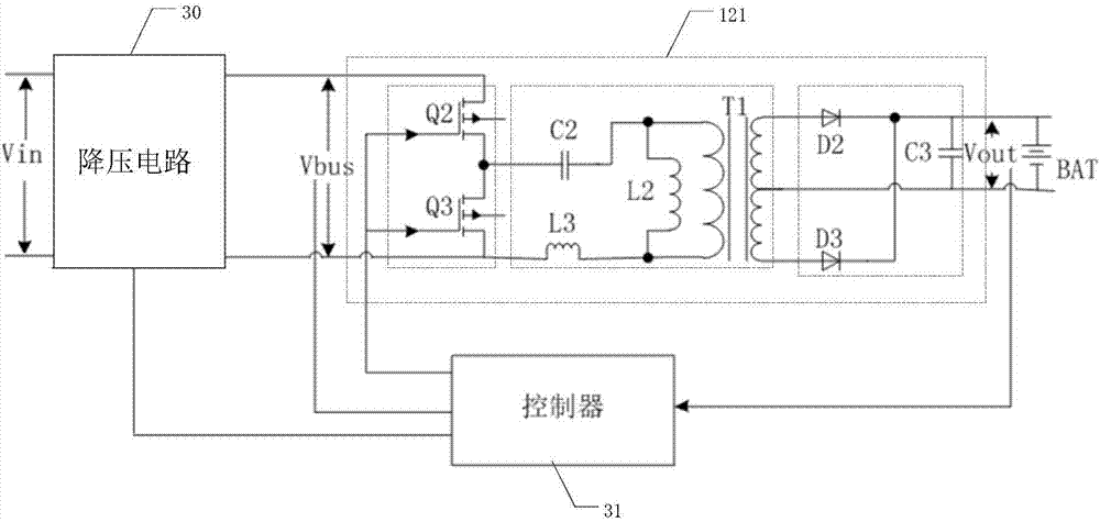
[0042] image 3 A structural diagram of a DCDC converter provided by an embodiment of the present invention. like image 3 As shown, it includes a step-down circuit 30 and a resonant unit 121 connected in series in sequence, and a controller 31 for controlling the step-down circuit 30 and the resonant unit 121 respectively. The step-down circuit 30 is used to step down the input voltage to input to the resonant The input terminal of the unit 121, the controller 31 is used to obtain the output terminal voltage of the resonance unit 121, and control the output voltage of the step-down circuit 30 and the switching frequency of the resonance unit 121 according to the target value of the output terminal voltage until the output terminal voltage reaches the target value , and control the switching frequency of the resonant unit 121 to be less than or equal to the resonant frequency after the output voltage reaches the target value, wherein the output terminal of the resonant unit 1...

Embodiment 2

[0054] Figure 4 A structural diagram of another DCDC converter provided by an embodiment of the present invention. On the basis of the above embodiments, as a preferred implementation manner, the step-down circuit 30 is specifically a Buck circuit, and the controller 31 controls the first switching tube in the Buck circuit.

[0055] like Figure 4 As shown, the Buck circuit includes a first switch tube Q11, a freewheeling diode D11, an inductor L11 and a capacitor C11, and the specific structure is as follows Figure 4 Shown, no more details.

[0056] In the prior art, the front end of the resonant unit 121 adopts a Boost circuit, which is a boost circuit, and the minimum output is limited to 750V due to input requirements. Moreover, for the application limitations of existing components, the output voltage of the Boost circuit is generally set at about 800V, which cannot be too high, otherwise it will be difficult to select components. Therefore, the voltage reduction ra...

Embodiment 3

[0062] On the basis of the above embodiments, the number of resonance units 121 is at least two. Figure 6 An application scenario diagram of a DCDC converter provided by an embodiment of the present invention. Figure 6 , take two as an example. The output end of each resonant unit 121 is respectively connected to the corresponding load (the first load F1 and the second load F2, both of which are fans), wherein the resonant unit 121 corresponding to the first load F1 includes Q4, Q5, C4, L5, L4, T2, D4, D5 and C5, and the resonance unit 121 corresponding to the second load F2 includes Q2, Q3, C2, L3, L2, T1, D2, D3 and C3.

[0063] The controller 31 is used to separately collect the output terminal voltages (Vout1 and Vout2) in each resonant unit 121, and control the output voltage of the step-down circuit 30 and the switching frequency of each resonant unit 121 according to the target value of each output terminal voltage until each resonant unit 121 The voltages at the ou...


PUM


Abstract

The invention discloses a DCDC converter, and the converter comprises a step-down circuit and a resonant unit, which are connected in series. The converter also comprises a controller for controlling the step-down circuit and the resonant unit. The step-down circuit is used for the step-down of an input voltage so as to input the voltage to the input end of the resonant unit. The controller is used for obtaining the output end voltage of the resonant unit, and controls the output voltage of the step-down circuit according to a target value of the output end voltage, controls the switching frequency of the resonant unit till the output end voltage reaches the target value, and controls the switching frequency of the resonant unit to be less than or equal to the resonant frequency after the output end voltage reaches the target value. Because the step-down range of the step-down circuit is wider, the switching frequency of the resonant unit can be guaranteed to be less than the resonant frequency in a longer time period. Therefore, the converter solves a problem that the switching frequency increases with the decrease of the target value in the prior art, thereby reducing the loss of a rectification diode. In addition, the invention also discloses a control method for the DCDC converter, and the beneficial effects are shown as above.

Description

technical field [0001] The invention relates to the field of electronic technology, in particular to a DC-DC converter and a control method thereof. Background technique [0002] With the rapid rise of new energy vehicles, electric vehicles are the main direction in the future. figure 1 An internal power supply structure diagram of an electric vehicle provided for the prior art. like figure 1 As shown, the high-voltage storage battery 10 is connected with the inverter 11 and the DCDC converter 12 respectively, the inverter 11 converts the electric energy output by the high-voltage storage battery 10 into alternating current output, and the DCDC converter 12 converts the electric energy into direct current for the storage battery 13 and the vehicle-mounted Appliance 14 is used. [0003] figure 2 A circuit diagram of a DCDC converter provided for the prior art. like figure 2 As shown, the DCDC converter 12 includes a boost boost circuit 120 , namely L1 , D1 , Q1 , and ...

Claims


Application Information

Patent Timeline
IPC IPC(8): H02M3/335
CPCH02M3/33523H02M1/0058Y02B70/10
Inventor 宋晨邓小康王凯董瑞勇
Owner SHENZHEN INVT ELECTRIC
Why Eureka
Try Eureka