
Novel medical waste incineration tail gas deacidifying tower

A technology of medical waste and deacidification tower, which is applied in the direction of gas treatment, climate change adaptation, climate sustainability, etc. Good acid effect, effect of increasing flow rate

Inactive Publication Date: 2017-12-19
曹欢
View PDF0 Cites 3 Cited by
  • Summary
  • Abstract
  • Description
  • Claims
  • Application Information

AI Technical Summary

Problems solved by technology

[0002] After the medical waste is incinerated by the incinerator, the viruses and germs are completely killed; the toxic and harmful substances are also completely decomposed into non-toxic and harmless compounds, so as to realize the harmlessness, stabilization and reduction of medical waste at the fastest speed. Disposal objectives: Disposing of medical waste by incineration is a method widely used in countries all over the world and in my country today. After waste is pyrolyzed and incinerated, harmful substances are effectively converted into non-toxic and harmless compounds, which avoids environmental pollution; however, due to medical waste There are various components, and a large amount of acid gas may be produced after incineration. The existing acid removal tower absorbs acid gas through alkaline solution. Due to the short residence time of the gas, the acid gas in the flue gas cannot be completely absorbed. , the efficiency of the deacidification tower is reduced, and the ideal deacidification effect cannot be achieved

Method used


Image

  • Novel medical waste incineration tail gas deacidifying tower
  • Novel medical waste incineration tail gas deacidifying tower
  • Novel medical waste incineration tail gas deacidifying tower

Examples


Embodiment Construction

[0014] The technical solution of this patent will be further described in detail below in conjunction with specific embodiments.

[0015] Embodiments of the present patent are described in detail below, examples of which are shown in the drawings, wherein the same or similar reference numerals designate the same or similar elements or elements having the same or similar functions throughout. The embodiments described below by referring to the figures are exemplary and are only used for explaining the patent, and should not be construed as limiting the patent.

[0016] In the description of this patent, it is to be understood that the terms "center", "upper", "lower", "front", "rear", "left", "right", "vertical", "horizontal", The orientation or positional relationship indicated by "top", "bottom", "inner", "outer", etc. is based on the orientation or positional relationship shown in the drawings, and is only for the convenience of describing this patent and simplifying the des...


PUM


Abstract

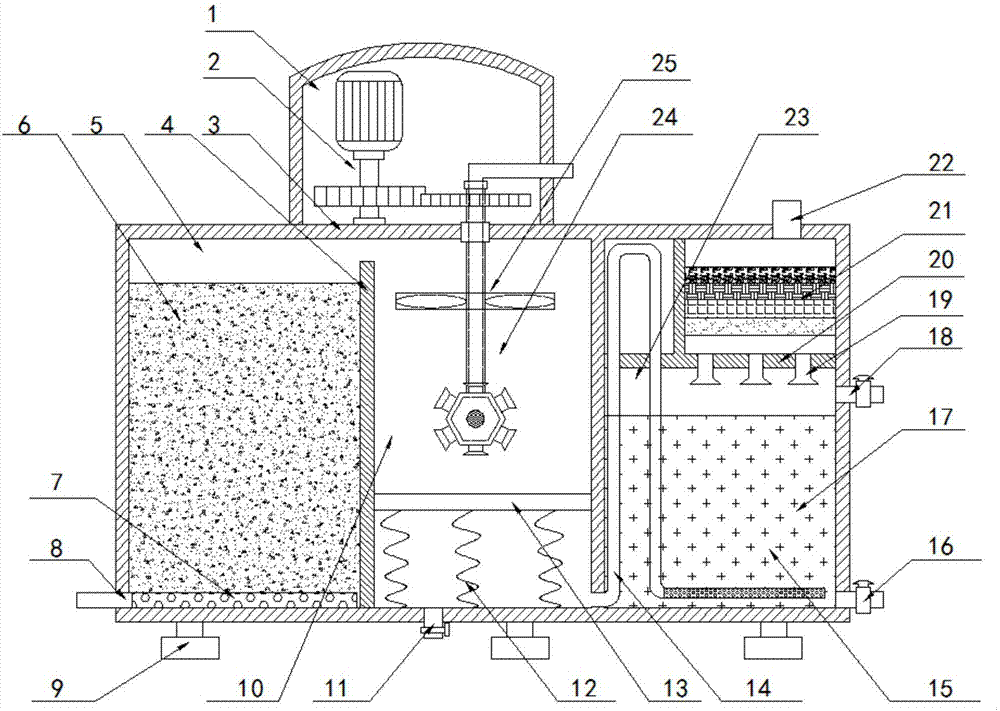
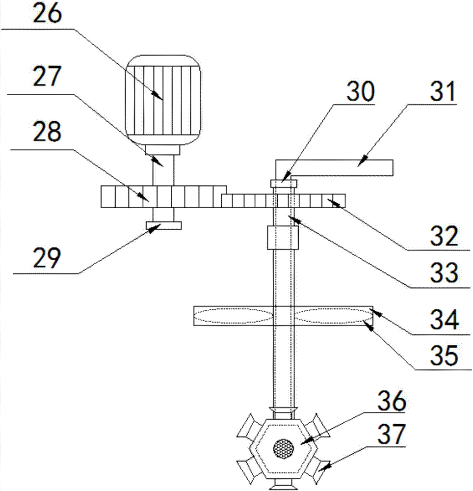
The invention provides a novel medical waste incineration tail gas deacidifying tower and belongs to the field of medical waste treatment equipment. The novel medical waste incineration tail gas deacidifying tower comprises a transmission device, a shell, an adsorption cavity, a first absorption cavity, a second absorption cavity and feet, wherein a piston, a spring, a rotary spray device and a gas absorption device are arranged in the first absorption cavity. According to the invention, through hierarchical setting of the adsorption cavity, the first absorption cavity and the second absorption cavity, acid substances in waste gas are removed step by step, and acid gases in flue gas are eliminated; moreover, the deacidifying tower greatly increases the time of the flue gas staying in the deacidifying tower, thus the deacidifying efficiency of the deacidifying tower is improved, and the deacidifying effect is good; through the rotary spray device and the gas absorption device, the flow rate of the acid gases and the contact area between an alkaline mist body and the acid gases are increased, and the neutralizing rate is raised; through a filtering device, particulate matters in the incineration tail gas are removed so as to prevent environmental pollution.

Description

technical field [0001] The invention relates to the field of medical waste treatment equipment, in particular to a novel medical waste incineration tail gas deacidification tower. Background technique [0002] After the medical waste is incinerated by the incinerator, the viruses and germs are completely killed; the toxic and harmful substances are also completely decomposed into non-toxic and harmless compounds, so as to realize the harmlessness, stabilization and reduction of medical waste at the fastest speed. Disposal objectives: Disposing of medical waste by incineration is a method widely used in countries all over the world and in my country today. After waste is pyrolyzed and incinerated, harmful substances are effectively converted into non-toxic and harmless compounds, which avoids environmental pollution; however, due to medical waste There are various components, and a large amount of acid gas may be produced after incineration. The existing acid removal tower abso...

Claims


Application Information

Patent Timeline
IPC IPC(8): B01D53/02B01D53/18B01D53/14B01D53/78B01D46/00B01D53/81B01D53/40B01D53/75
CPCB01D46/00B01D53/02B01D53/1406B01D53/1456B01D53/18B01D53/40B01D53/75B01D53/78B01D53/81B01D2258/0283Y02A50/2351
Inventor 曹欢汤沛东
Owner 曹欢
Learn More