
Home appliance refrigeration pipe connector positioning and welding clamp

A technology for positioning welding and refrigeration pipes, used in household appliances, manufacturing tools, welding equipment, etc., can solve the problems of poor welding forming quality, difficult to accurately control concentricity, large pipes, etc., to ensure product availability and improve resources. Utilization rate, the effect of improving the process effect

Inactive Publication Date: 2017-12-19
谢兴艺
View PDF4 Cites 4 Cited by
  • Summary
  • Abstract
  • Description
  • Claims
  • Application Information

AI Technical Summary

Problems solved by technology

[0002] With the development and progress of society, people's living standards are also improving with the popularization of home appliances. Many home appliance pipes need to be welded during home appliance production. Fixture, the welding error of these two methods is large, the concentricity is difficult to control accurately, and the longer the pipe is, the greater the error is, and the concentricity cannot be accurately controlled for pipes of different lengths, and the welding forming quality is prone to occur when the error is large The effect is poor, the welding strength cannot meet the process requirements, and defects such as cracks, wrong edges, and undercuts are prone to occur, wasting materials

Method used


Image

  • Home appliance refrigeration pipe connector positioning and welding clamp
  • Home appliance refrigeration pipe connector positioning and welding clamp
  • Home appliance refrigeration pipe connector positioning and welding clamp

Examples


Embodiment Construction

[0015] The following will clearly and completely describe the technical solutions in the embodiments of the present invention with reference to the accompanying drawings in the embodiments of the present invention. Obviously, the described embodiments are only some, not all, embodiments of the present invention.

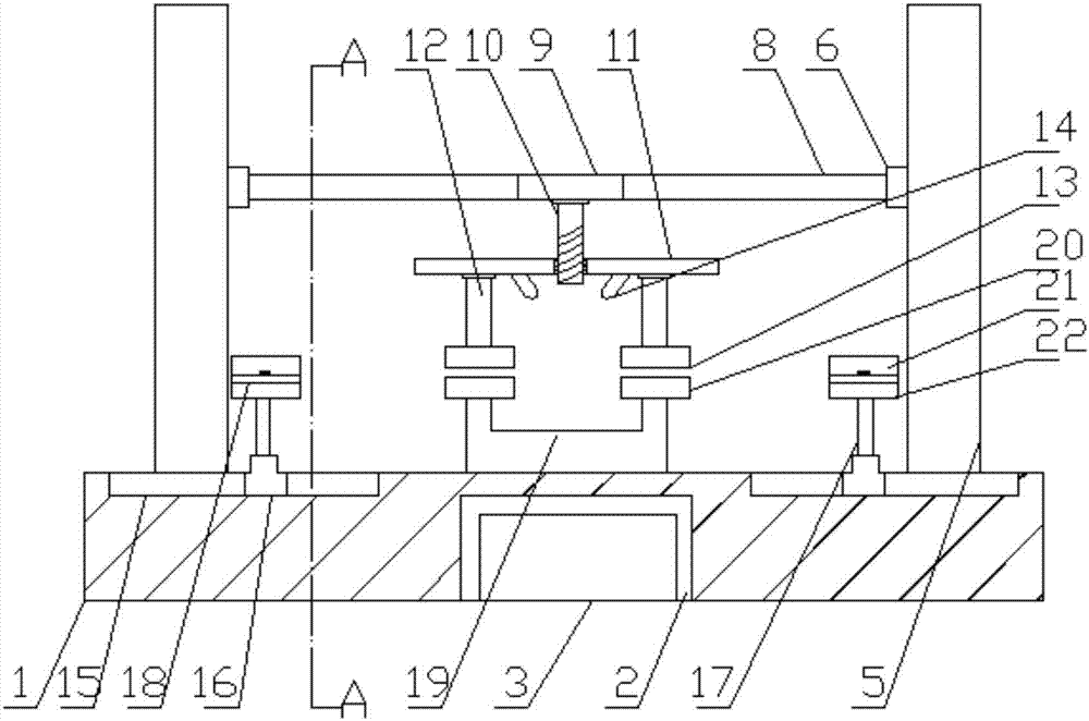
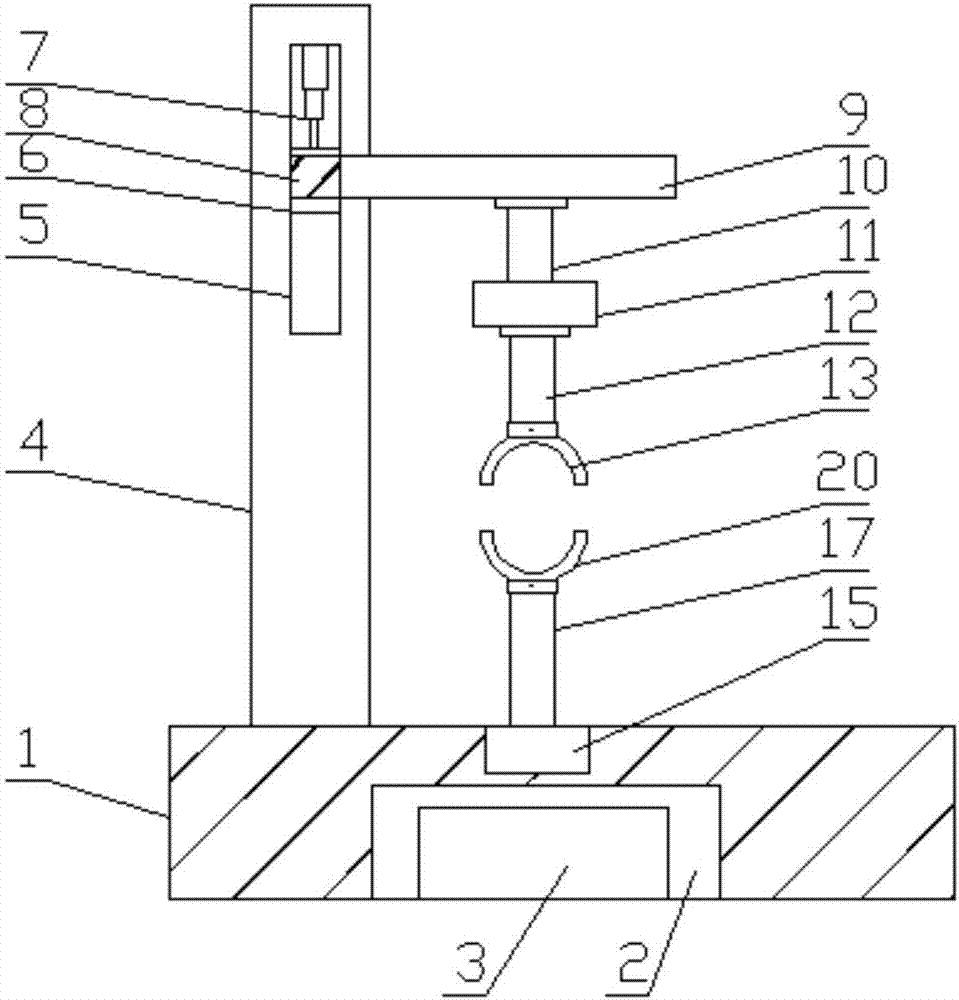
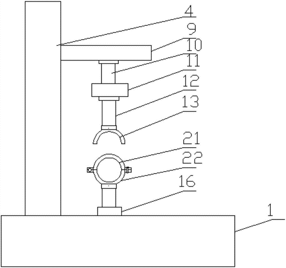
[0016] refer to Figure 1-3 , a positioning welding fixture for the interface of refrigeration pipes of home appliances, comprising a base 1, a chamber 2 is provided in the base 1, a water tank 3 is provided in the chamber 2, two vertical boards 4 are provided on the upper end of the base 1, and the two vertical boards 4 are arranged in parallel with each other, and the first chute 5 is provided on the opposite side walls of the two vertical plates 4, and the first convex slider 6 is arranged in the first chute 5, and the top surfaces of the two first chute 5 Both are connected with a hydraulic cylinder 7, and the piston rod of the hydraulic cylinder 7 is set vertica...


PUM


Abstract

The invention discloses a home appliance refrigeration pipe connector positioning and welding clamp which comprises a base. A chamber is arranged in the base. A water tank is arranged in the chamber. Two vertical plates are arranged at the upper end of the base in parallel. First sliding grooves are formed in the opposite side walls of the two vertical plates. First convex sliding blocks are arranged in the first sliding grooves, and the top faces of the two first sliding grooves are both connected with hydraulic cylinders. Piston rods of the hydraulic cylinders are arranged downwards vertically. The lower ends of the piston rods of the hydraulic cylinders are connected with the upper ends of the first convex sliding blocks. A first transverse plate is arranged between the two vertical plates. The two ends of the first transverse plate are connected with the side walls of the two first convex sliding blocks correspondingly. The side wall of the first transverse plate is connected with a transverse rod which is close to the middle of the first transverse plate. The lower end of the transverse rod is fixedly connected with a threaded rod, and the threaded rod is arranged at the end, away from the first transverse plate, of the transverse rod. According to the home appliance refrigeration pipe connector positioning and welding clamp, the concentricity of two welded pipes can be controlled more accurately, and a welding point can be cooled rapidly.

Description

technical field [0001] The invention relates to the technical field of welding jigs, in particular to a positioning welding jig for refrigeration pipe joints of household appliances. Background technique [0002] With the development and progress of society, people's living standards are also improving with the popularization of home appliances. Many home appliance pipes need to be welded during home appliance production. Fixture, the welding error of these two methods is large, the concentricity is difficult to control accurately, and the longer the pipe is, the greater the error is, and the concentricity cannot be accurately controlled for pipes of different lengths, and the welding forming quality is prone to occur when the error is large The effect is poor, the welding strength cannot meet the process requirements, and defects such as cracks, wrong edges, and undercuts are prone to occur, and materials are wasted. Contents of the invention [0003] The purpose of the ...

Claims


Application Information

Patent Timeline
Patent Type & Authority Applications(China)
IPC IPC(8): B23K37/053
CPCB23K37/0533B23K37/003B23K2101/06
Inventor 谢兴艺
Owner 谢兴艺
Learn More