Shaft-like workpiece storing and feeding device

A shaft workpiece and feeding device technology, applied in the field of automatic processing, can solve the problems of difficult control of feeding accuracy, complex feeding structure, and low feeding efficiency, and achieve short moving time and stroke, simple device structure, and high feeding efficiency. Effect

Pending Publication Date: 2017-12-19
宁波宫铁智能科技有限公司
View PDF19 Cites 4 Cited by
  • Summary
  • Abstract
  • Description
  • Claims
  • Application Information

AI Technical Summary

Problems solved by technology

[0004] Existing feeding equipment, for example, the invention patent with the application number 201510151194.X discloses a press-in type one-way feeding mechanism, this feeding structure realizes the function of concentrating and sending out shaft workpieces sequentially, but At the same time, the following technical problems exist. 1. This kind of feeding structure is more complicated, the volume is larger, the space occupied is larger, and the use restriction is larger. The movement on the mechanism is long, resulting in low feeding efficiency of shaft workpieces; 2. Traditional shaft workpiece processing equipment usually clamps shaft workpieces through the clamping manipulator structure, and then sends them into the processing equipment , so as to realize automatic speech feeding. However, since the shaft workpiece is processed in a cylindrical processing equipment, the workpiece needs to enter from one end of the processing equipment and come out from the other end. Ensure that the workpiece is accurately fed into the processing equipment; 3. Actions such as clamping, placing, and moving of the manipulator cause a long feeding stroke and process, resulting in low feeding efficiency. Similarly, the moving space of the manipulator and the shaft workpiece Occupies a large space, resulting in a large space required for feeding and poor flexibility in use

Method used


Image

  • Shaft-like workpiece storing and feeding device
  • Shaft-like workpiece storing and feeding device
  • Shaft-like workpiece storing and feeding device

Examples


Embodiment Construction

[0038] The following are specific embodiments of the present invention and in conjunction with the accompanying drawings, the technical solutions of the present invention are further described, but the present invention is not limited to these embodiments.

[0039] The present invention improves the existing material storage and feeding equipment, aiming at simplifying the structure of the traditional equipment, reducing its occupied space, shortening the moving stroke of the workpiece, and improving the feeding efficiency and accuracy of the workpiece.

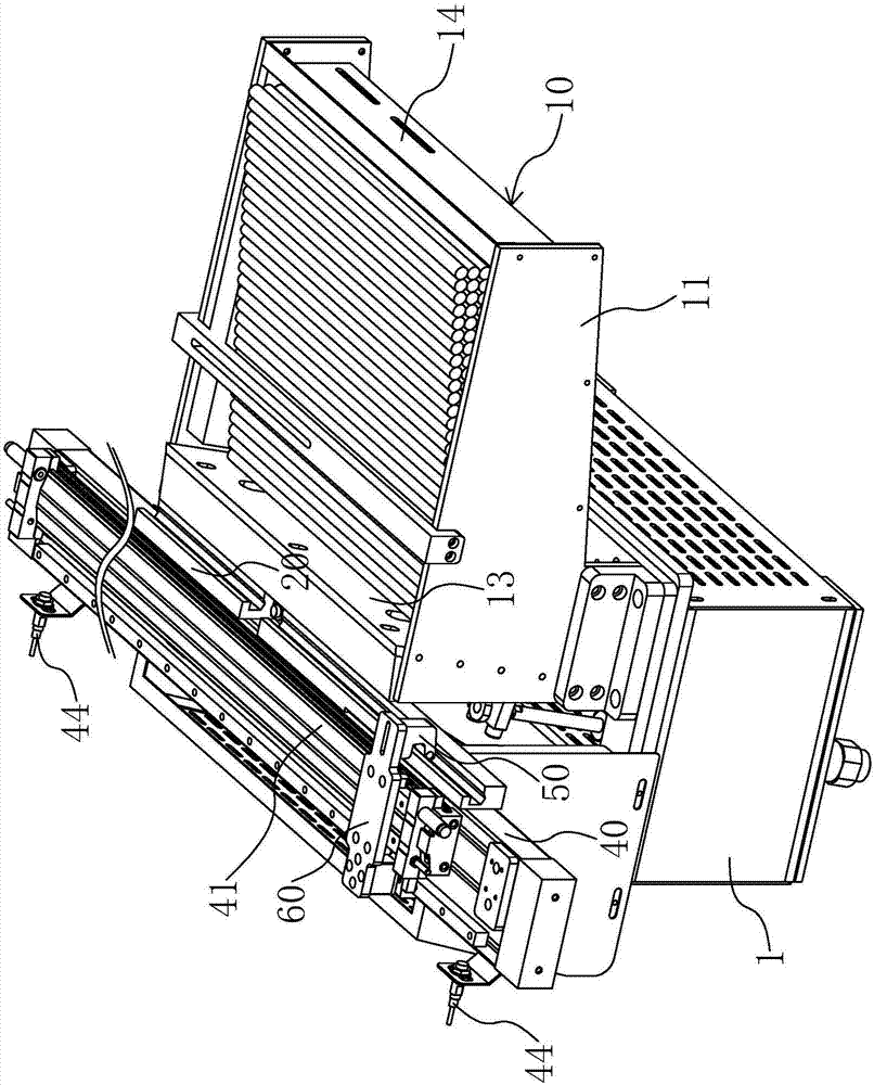
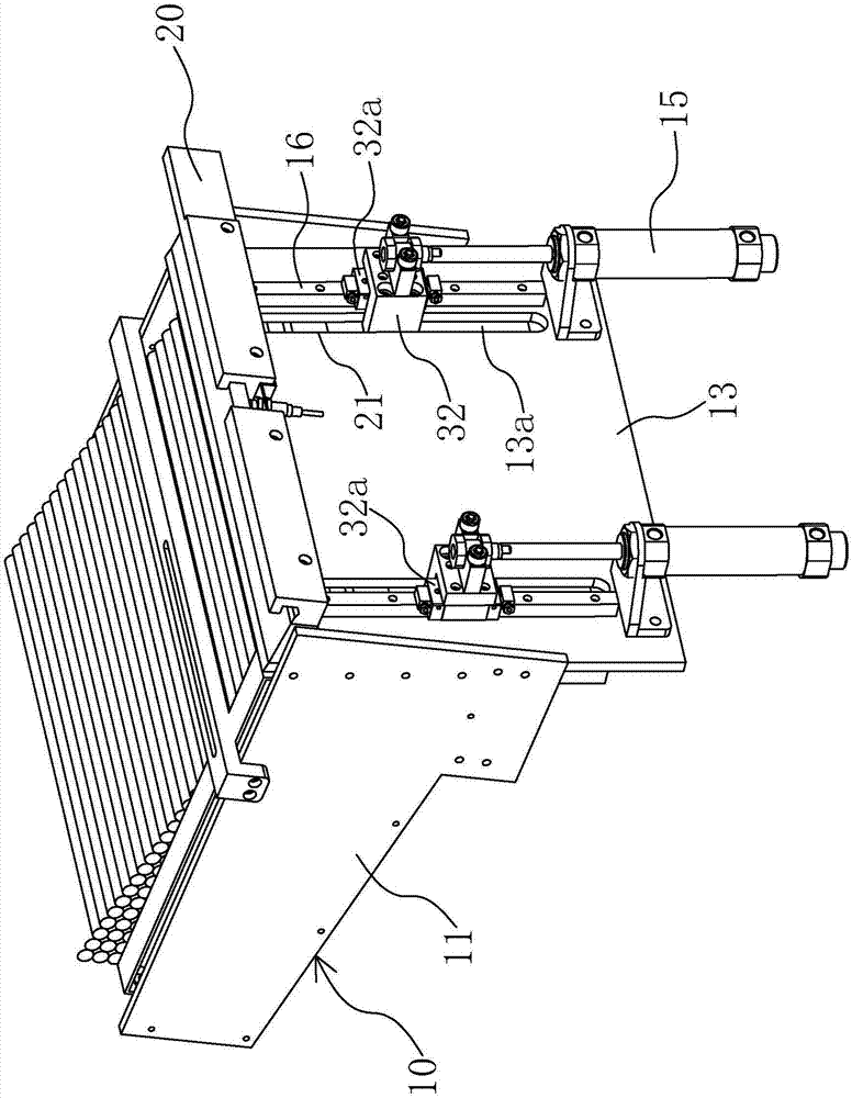
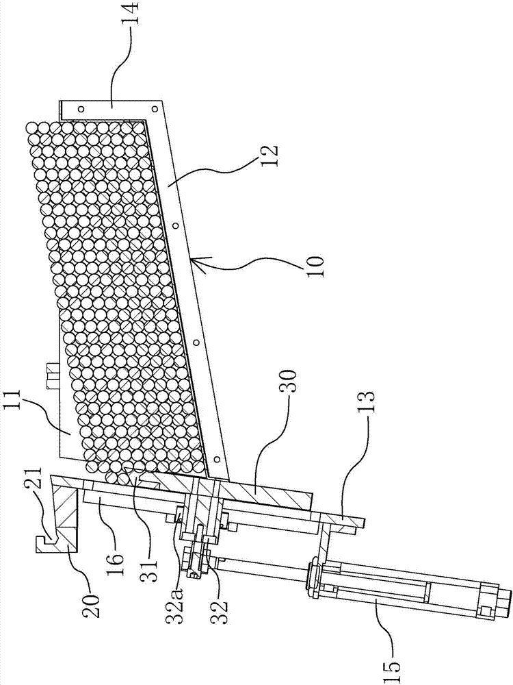
[0040] Such as Figure 1 to Figure 4 As shown, a shaft workpiece storage and feeding device of the present invention is installed on the feed end side of the processing equipment during its work, and it includes a storage rack 10, a stock stand 20, a pushing plate 30, a mounting table 40 and Push block 50.

[0041] The material storage rack 10 is horizontally arranged, and it is fixed on a frame 1, and its interior is hollow...


PUM


Abstract

The invention provides a shaft-like workpiece storing and feeding device, and belongs to the technical field of automatic machining. The technical problems of large size, low feeding efficiency and low feeding precision of existing storing and feeding equipment are solved. The shaft-like workpiece storing and feeding device comprises a storing frame, a material preparing base, a material pushing plate, an installing table and a pushing block, wherein the storing frame is used for storing workpieces; the material preparing base is fixedly connected with one end of the storing frame, and a material trough is formed in the material preparing base; the material pushing plate is arranged in the storing frame and movably connected with the storing frame; the installing table is arranged horizontally and adjacent to one end of the storing frame; and the pushing block is movably arranged on one side of the installing block and adjacent to the material preparing base, and the pushing block extends into the material trough. The pushing plate can move in the storing frame and can push the workpieces in the storing frame into the material trough. The pushing block can move on the installing table and can push the workpieces out of the material trough. Through moving of the material pushing plate, the workpieces in the storing frame can be pushed into the material trough in the material preparing base in sequence, the workpieces are conveniently conveyed into machining equipment, and the shaft-like workpiece storing and feeding device is simple in structure, small in occupied area and flexible in using.

Description

technical field [0001] The invention belongs to the technical field of automatic processing, and relates to a shaft workpiece storage and feeding device. Background technique [0002] Shaft workpieces are common workpieces in the field of mechanical processing. With the continuous development of automation, shaft workpieces have also realized automatic processing. [0003] Normally, the processing of shaft workpieces generally includes storage and feeding equipment, processing equipment, and output equipment. The shaft workpieces are stored in the storage and feeding (or feeding) equipment. At the same time, the storage and The feeding equipment can send the shaft workpieces into the processing equipment for processing, and the shaft workpieces are processed into finished workpieces and sent to the discharge equipment, and are collected uniformly by the discharge equipment, so as to realize the automatic processing of shaft workpieces. [0004] Existing feeding equipment, f...

Claims


Application Information

Patent Timeline
Patent Type & Authority Applications(China)
IPC IPC(8): B65G65/44
CPCB65G65/44B65G2201/0217
Inventor 朱建群
Owner 宁波宫铁智能科技有限公司
Why Eureka
Try Eureka