Bituminous pavement automatic repairing device for bituminous concrete road

A technology of asphalt concrete and asphalt pavement, which is applied in road repair, roads, roads, etc., can solve problems that affect the work process, take a long time, and cause safety hazards, and achieve the effect of improving work efficiency and reducing labor intensity

Inactive Publication Date: 2017-12-19
丁建丽
View PDF0 Cites 23 Cited by
  • Summary
  • Abstract
  • Description
  • Claims
  • Application Information

AI Technical Summary

Problems solved by technology

[0003] In order to solve the above problems, the present invention provides an asphalt pavement automatic repair equipment for asphalt concrete roads, which can solve the problem of manual marking and cutting on the ground in the process of repairing the ground on the existing asphalt roads, and then shatter the ground with the help of props. The waste materials were excavated manually and then grouted and rolled. During the repair process, there were deviations in the manual scribing and cutting of the staff, which affected the work process. At the same time, there were safety hazards. The dead corner area cannot be completely shattered. The construction personnel use tools to excavate and remove the ground, which takes a long time and cannot fully excavate the surrounding small areas. People use existing tools to grout the construction area and then use rolling props Rolling the ground, such as high labor intensity and low efficiency, can realize the automatic repair function of asphalt pavement, ensure the safety of personnel, and there is no error. Automatic cutting, crushing, excavation, grouting, rolling, without manual operation, It has the advantages of simple operation, low labor intensity and high work efficiency

Method used


Image

  • Bituminous pavement automatic repairing device for bituminous concrete road
  • Bituminous pavement automatic repairing device for bituminous concrete road
  • Bituminous pavement automatic repairing device for bituminous concrete road

Examples


Embodiment Construction

[0044] In order to make the technical means, creative features, goals and effects achieved by the present invention easy to understand, the present invention will be further described below in conjunction with specific illustrations. It should be noted that, in the case of no conflict, the embodiments in the present application and the features in the embodiments can be combined with each other.

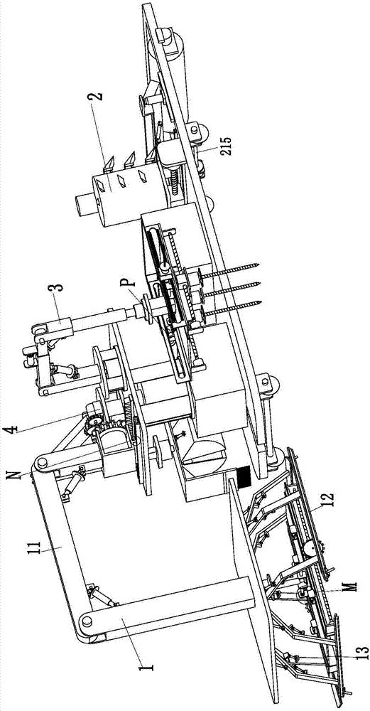
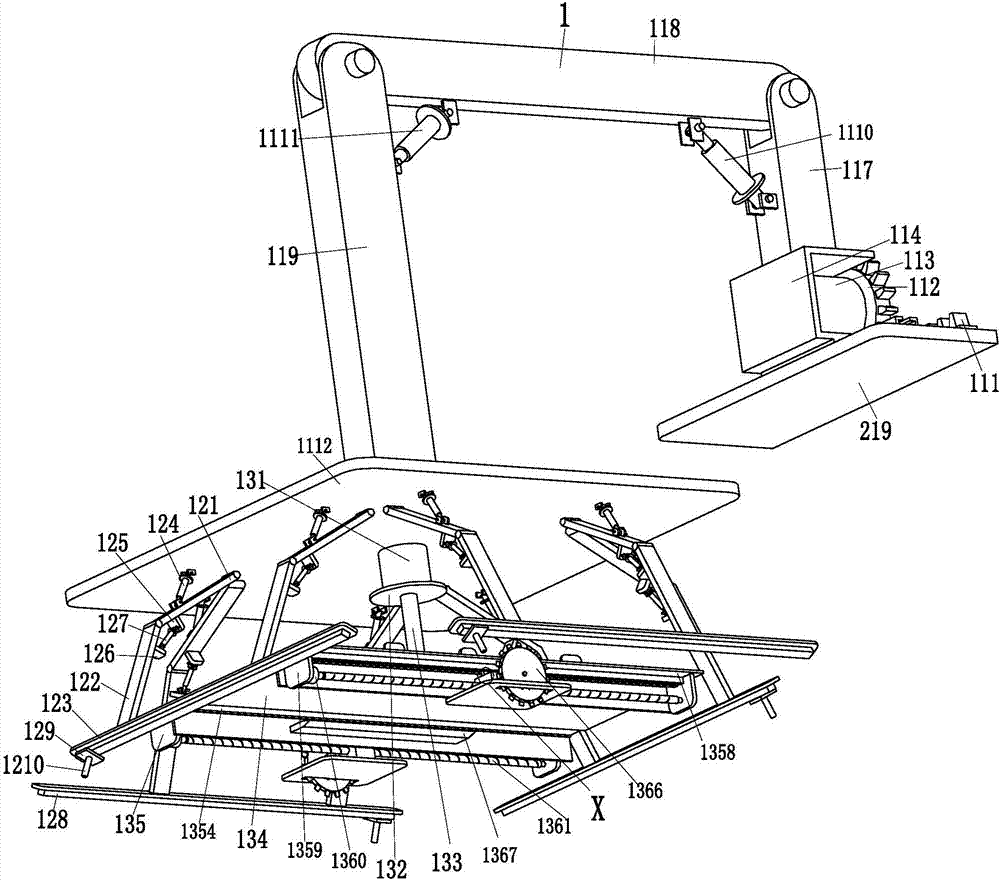
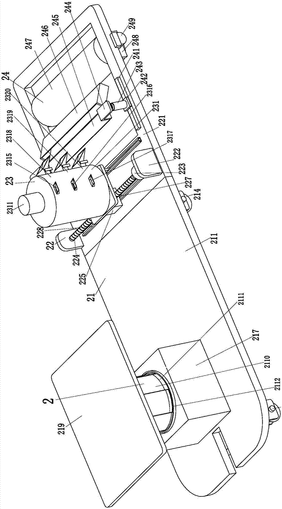
[0045] Such as Figure 1 to Figure 13 As shown, an asphalt pavement automatic repair equipment for asphalt concrete roads includes a cutting device 1, a material conveying and rolling moving device 2, a crushing device 3 and a grabbing device 4, and the cutting device 1 plays a role in cutting maintenance roads. function, the conveying and rolling moving device 2 plays the role of conveying and rolling on the ground, the crushing device 3 plays the role of crushing the maintenance road, and the grabbing device 4 recycles the crushed waste materials. The cutting device 1 is installed...


PUM


Abstract

The present invention relates to an asphalt pavement automatic repair equipment for asphalt concrete roads, comprising a cutting device, a material conveying and rolling moving device, a crushing device and a grabbing device, and the cutting device is installed on the upper end of the conveying and rolling moving device On the front side of the conveyor, a crushing device is installed on the right side of the upper end of the material conveying rolling mobile device, and a grabbing device is installed on the upper left side of the material conveying rolling mobile device. The present invention can solve the problem that in the process of repairing the ground on the existing asphalt road, the waste materials are dug away manually and then grouted and rolled. There are deviations in the manual marking and cutting of the staff, and there are safety hazards at the same time. The construction personnel shatter the ground with the help of tools At the same time, the dead corner areas on the four sides cannot be completely shattered, and the surrounding small areas cannot be fully excavated. People use existing tools to grout the construction area and then use rolling props to roll the ground. The work is labor intensive and efficient. Low-level problems can realize the automatic repair function of asphalt pavement.

Description

technical field [0001] The invention relates to the technical field of asphalt pavement repair equipment, in particular to an asphalt pavement automatic repair equipment for asphalt concrete roads. Background technique [0002] The asphalt pavement of asphalt concrete has less wind noise, less wear on the tread of the car, and is also conducive to improving the grip of the car. At the same time, it has better toughness, good compressive resistance and stretchability, and can better adapt to not very Stable roadbed makes asphalt roads popular with people, but the process of repairing damaged asphalt roads is cumbersome and complicated. How to repair asphalt ground has become a big problem. At present, people draw lines on the ground manually and then use props to vibrate the ground. The waste materials are excavated manually and then grouted and rolled. During the repair process, there may be deviations in the manual scribing and cutting of the staff, which affects the work p...

Claims


Application Information

Patent Timeline
Patent Type & Authority Applications(China)
IPC IPC(8): E01C23/06E01C23/09E01C23/12E01C19/48
CPCE01C23/06E01C19/48E01C23/0933E01C23/127
Inventor 丁建丽
Owner 丁建丽
Why Eureka
Try Eureka