Pressure holding fixture

A clamping and clamping technology, which is applied in the direction of material gluing, connecting components, mechanical equipment, etc., can solve the problems of easy wear or breakage of buckles, high development cost of clamping fixtures, and low efficiency of disassembly and assembly, so as to achieve easy disassembly and assembly, Save jig cost and save space

Inactive Publication Date: 2017-12-19
WINGTECH COMM
View PDF5 Cites 10 Cited by
  • Summary
  • Abstract
  • Description
  • Claims
  • Application Information

AI Technical Summary

Problems solved by technology

[0004] like figure 1 As shown, the existing upper and lower mold pressure-holding fixtures are composed of an upper mold and a lower mold. One set of fixtures needs to open two sets of molds. The development cost of the fixture is high and the space is relatively large.
[0005] The buckle locking method requires a large force to deform the buckle when

Method used


Image

  • Pressure holding fixture
  • Pressure holding fixture
  • Pressure holding fixture

Examples


Embodiment 1

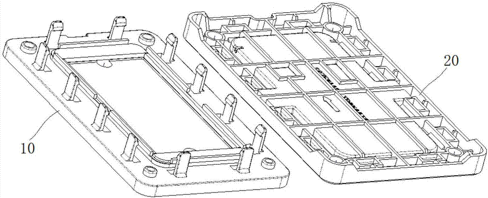
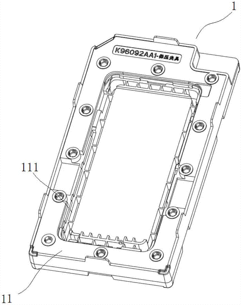
[0029] see Figure 2 to Figure 9 , the present invention discloses a pressure maintaining fixture, which comprises: several clamp units 1, the middle part of the first surface 11 of each clamp unit 1 is provided with a groove 111 for placing a pressed object, each clamp unit 1 The first surface 11 of each clamp unit 1 is used as the lower clamp surface, and the second surface 12 of each clamp unit 1 is used as the upper clamp surface. The upper clamp surface of one clamp unit 1 can cooperate with the lower clamp surface of another clamp unit 1 to complete the pressure maintaining action (such as Figure 7 , Figure 9 shown).

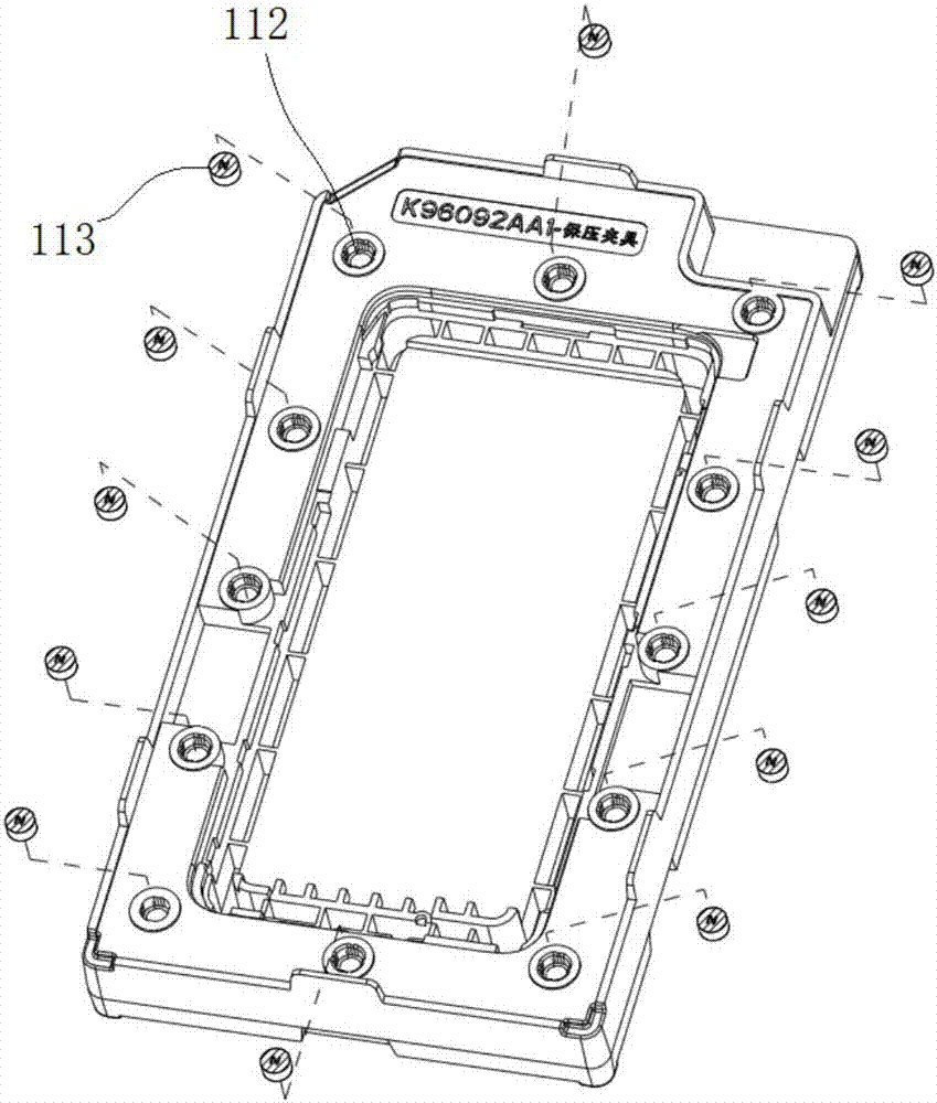
[0030] The periphery of the groove 111 is provided with several circular grooves 112, and the first magnetic mechanism 113 is arranged in the circular groove 112; the second surface 12 of the clamp unit 1 is provided with several circular grooves 122, and the circular grooves A second magnetic mechanism 123 opposite to the first magnetic mechanism 113...


PUM

PropertyMeasurementUnit
Diameteraaaaaaaaaa

Abstract

The invention discloses a pressure holding fixture. The pressure holding fixture comprises a plurality of fixture units. The middle portion of the first surface of each fixture unit is provided with a groove used for containing a pressed object. The first surface of each fixture unit serves as a lower fixture surface. The second surface of each fixture unit serves as an upper fixture surface. The upper fixture surface of one fixture unit can be matched with the lower fixture surface of the other fixture unit to complete the pressure holding action. The periphery of each groove is provided with a plurality of first magnetic mechanisms. The second surface of each fixture unit is provided with a plurality of second magnetic mechanisms with the magnetism opposite to the first magnetic mechanisms; or, the second surface of each fixture unit is provided with a plurality of metal absorption mechanisms capable of being attracted by the first magnetic mechanisms. The second magnetic mechanisms are absorbed by the corresponding g first magnetic mechanisms in a matched mode. According to the pressure holding fixture provided by the invention, the obverse sides serve as lower fixture bodies, and the reverse sides serve as upper fixture bodies. The fixture structure is simplified. The mold and fixture cost is saved (originally two fixtures are needed, and now only one fixture is needed.).

Description

technical field [0001] The invention belongs to the technical field of pressure maintaining equipment, and relates to a pressure maintaining fixture, in particular to a pressure maintaining fixture for a mobile phone. Background technique [0002] When the narrow frame of the mobile phone TP or the back glue cannot meet the die-cutting and bonding strength, it will be applied to the structural hot-melt adhesive dispensing process. The hot melt glue dispensing process is as follows: heat the glue to about 120 degrees, extrude it onto the casing through a glue dispenser, bond and solidify with TP, and fix it with a pressure holding fixture. The curing time is about 4 hours. [0003] The principle of the pressure-holding fixture: the pre-pressed front shell assembly is placed between the upper and lower clamping fixtures of the existing pressure-holding fixture. Press to cure the structural adhesive between the shell and TP to achieve optimal adhesion and consistent height dim...

Claims


Application Information

Patent Timeline
IPC IPC(8): F16B11/00
CPCF16B11/006
Inventor 陈桃林肖礼慕明刚刘晟段胜中
Owner WINGTECH COMM
Why Eureka
Try Eureka