Eureka AIR delivers breakthrough ideas for toughest innovation challenges, trusted by R&D personnel around the world.

Automotive headlamp cooling system

A technology for automotive headlights and cooling systems, applied in the field of automotive headlight cooling systems, can solve problems such as easy dust accumulation, stuck, non-rotating, and failure, and achieves convenient installation and maintenance, good cooling effect, and fast cooling speed Effect

Pending Publication Date: 2017-12-19
HESHAN JIANHAO LIGHTING IND
View PDF5 Cites 0 Cited by
  • Summary
  • Abstract
  • Description
  • Claims
  • Application Information

AI Technical Summary

Problems solved by technology

However, at present, one of the bottlenecks facing the development of LED lights is heat dissipation. For high-power LED headlights, as the power continues to increase, the temperature of the LED internal chips will gradually rise, and the LED internal chips and The performance of other devices will decline as the temperature rises, or even fail, which will eventually cause the LED device to fail to work
At present, the heat dissipation of most LED lights relies on the installation of fans for passive heat dissipation. However, for LED headlights, fan heat dissipation can only be one of the auxiliary functions, and cannot completely rely on cooling fans. It is easy to accumulate dust, if it is not cleaned in time, it is easy to get stuck, and the life of the fan is generally only 9000 rpm
In addition, LED headlights are also dissipated through the coolant and circulation system of the car engine itself, but usually the coolant temperature of the car can reach 70-80°C, or even 100°C; The coolant of the engine is always circulating when the car is running, so that the LED lamps are also in a relatively high temperature environment when they are not in use, which affects their service life and luminous effect

Method used


Image

  • Automotive headlamp cooling system
  • Automotive headlamp cooling system

Examples


Embodiment Construction

[0018] The following will clearly and completely describe the technical solutions in the embodiments of the present invention with reference to the accompanying drawings in the embodiments of the present invention. Obviously, the described embodiments are some of the embodiments of the present invention, but not all of them. Based on the embodiments of the present invention, all other embodiments obtained by persons of ordinary skill in the art without creative efforts fall within the protection scope of the present invention.

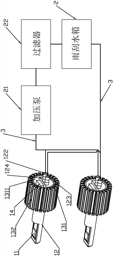
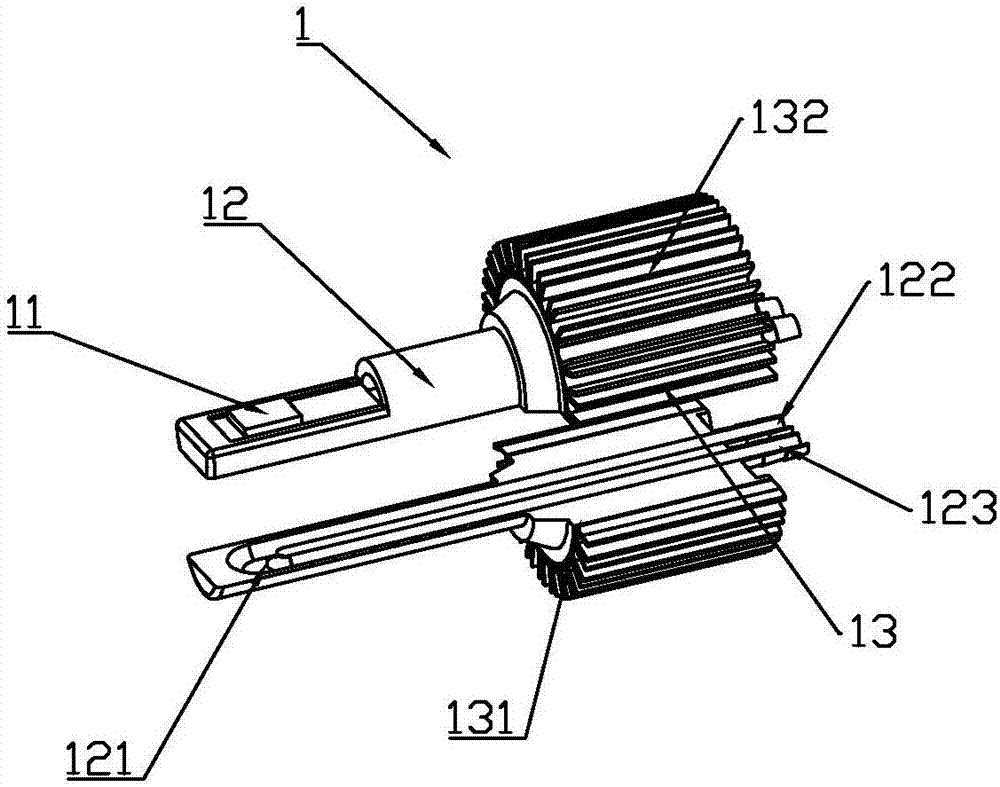
[0019] refer to figure 1 and figure 2 As shown, the present embodiment includes a headlight group 1 and a water tank 2, the water tank 2 is provided with a booster pump 21 for controlling water circulation, and a pipeline 3 is connected between the headlight group 1 and the water tank 2. In this embodiment, the water tank 2 is the wiper water tank, which uses the wiper water tank as the cooling water source of the circulating heat dissipation system....


PUM


Abstract

The invention discloses an automotive headlamp cooling system and relates to the technical field of automotive lighting. The automotive headlamp cooling system comprises a headlamp set and a water tank; the water tank is provided with a pressure pump for controlling water flow circulation; a pipeline is connected between the headlamp set and the water tank; the water tank is a windscreen wiper water tank; the headlamp set comprises two headlamps; each headlamp comprises an LED lamp, a heat conducting strip, a cooling part and a control board; the heat conducting strips are internally provided with circular cooling pipelines in a penetrating mode; a water inlet and a water outlet are formed in the end, away from the corresponding LED lamp, of each heat conducting strip; each cooling part comprises a cooling tube and cooling fins; a through hole is formed in each cooling tube; the end, close to the corresponding control board, of each heat conducting strip is contained in the corresponding through hole; and the cooling fins are arranged along the external circumference of the cooling tubes. Circular water is led into the heat conducting strips and passes through the bottom faces of the LED lamps to form the circular cooling system, and the cooling effect is good; and the pressure pump is used for connecting water in the windscreen wiper water tank into the cooling system, the cooling speed is high, the structure is simple, and installation and maintenance are convenient.

Description

technical field [0001] The invention relates to the technical field of automobile lighting, in particular to an automobile headlamp cooling system. Background technique [0002] LED is favored by the majority of users for its small size, low power consumption, environmental protection, durability, and rich light source colors. However, at present, one of the bottlenecks facing the development of LED lights is heat dissipation. For high-power LED headlights, as the power continues to increase, the temperature of the LED internal chips will gradually rise, and the LED internal chips and The performance of other devices will decrease as the temperature rises, or even fail, which will eventually cause the LED device to fail to work. At present, the heat dissipation of most LED lights relies on the installation of fans for passive heat dissipation. However, for LED headlights, fan heat dissipation can only be one of the auxiliary functions, and cannot completely rely on cooling ...

Claims


Application Information

Patent Timeline
Patent Type & Authority Applications(China)
IPC IPC(8): F21S8/10F21V29/56F21V29/77F21W101/02F21W101/10F21Y115/10
CPCF21V29/59F21V29/77F21Y2115/10
Inventor 黄国豪
Owner HESHAN JIANHAO LIGHTING IND
Why Eureka
Eureka Blog
Learn More