Optical scanning sensor

An optical scanning and sensor technology, applied in the field of optical scanning sensors, to achieve the effects of increasing the distance measurement range, strong convergence effect, and increasing the effective light receiving area

Inactive Publication Date: 2017-12-19
BEIJING FREEMEASURE OPTOELECTRONICS TECH CO LTD
View PDF6 Cites 6 Cited by
  • Summary
  • Abstract
  • Description
  • Claims
  • Application Information

AI Technical Summary

Problems solved by technology

[0003] The main purpose of the present invention is to provide a compact transceiver coaxial optical scanning senso

Method used


Image

  • Optical scanning sensor
  • Optical scanning sensor
  • Optical scanning sensor

Examples


Example Embodiment

[0039] The following description is used to disclose the present invention so that those skilled in the art can implement the present invention. The preferred embodiments in the following description are only examples, and those skilled in the art can think of other obvious variations. The basic principles of the present invention defined in the following description can be applied to other embodiments, modifications, improvements, equivalents, and other technical solutions that do not depart from the spirit and scope of the present invention.

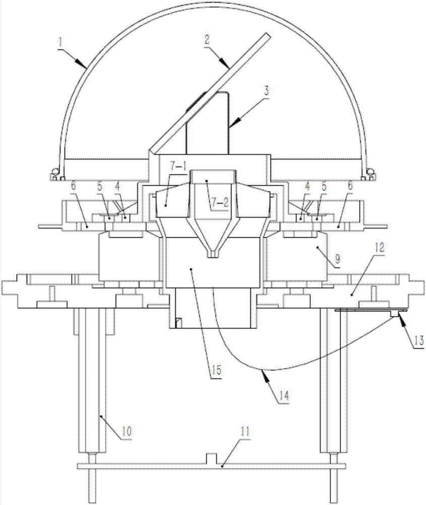
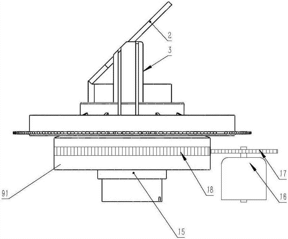
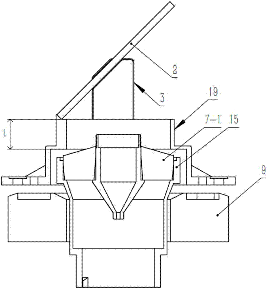
[0040] figure 1 Shown is an optical scanning sensor provided by the present invention. Such as figure 1 As shown, an optical scanning sensor includes a spherical transparent cover 1, a reflecting mirror 2, a reflecting mirror holder 3, a spatial angle positioning disk 6, a hollow motor 9, a receiving lens 7-1, a basic transmitting lens 7-2, and a receiving lens Lens barrel 15, light receiver circuit board 11, light receiver circuit board...


PUM


Abstract

The invention provides an optical scanning sensor, which comprises a light source, a light casting unit, a light receiving unit, a light receiver, a deflection unit, a curved light transmission cover, a rotation unit, and an angle encoder, wherein the deflection unit comprises a reflector and a reflector support; the rotation unit comprises a hollow part and a driving element; the light casting unit comprises a basic light casting unit, and the basic light casting unit and the light receiving unit are a transmitting-receiving coaxial optical system and are located at the same side of the reflector, and light reflected by a target area and deflected by the reflector enters the light receiver through a through hole in the hollow part; and the reflector is fixed above the rotation unit through the reflector support and rotates for 360 DEG under driving of the driving element.

Description

technical field [0001] The invention relates to an optical scanning sensor. Background technique [0002] The distance-measuring optical scanning sensor (generally called distance-measuring laser radar, Lidar) needs to complete one or more specific spatial sections (plane section or cone section) of the use environment with a fixed scanning frequency (such as 25Hz). The basic measurement method is the "time-of-flight" measurement method, that is, the laser light wave is emitted at a specific spatial angle, and the laser light wave reflected by the target surface at this spatial angle is detected at the same time, and the laser light wave is calculated from emission to reflection. For the returned flight time, the distance value is obtained through Time-Distance-Conversion (TDC). The acquired original measurement data is expressed in spatial polar coordinates, with a fixed point in the optical structure of the scanning sensor (generally located on the rotation axis of the ro...

Claims


Application Information

Patent Timeline
IPC IPC(8): G01S7/481
CPCG01S7/4817G01S7/481G01S17/08
Inventor 李毅周泽明
Owner BEIJING FREEMEASURE OPTOELECTRONICS TECH CO LTD
Why Eureka
Try Eureka