Supercharge Your Innovation With Domain-Expert AI Agents!

Negative-voltage charge pump

A charge pump and negative pressure technology, which is applied to electrical components, conversion equipment without intermediate conversion to AC, output power conversion devices, etc., can solve the problem of charge backflow, clock control circuit 2 cannot correctly transmit CLK/CLKB low level, etc. problem, to achieve the effect of increasing the output current value and improving the stability of the circuit

Active Publication Date: 2017-12-19
SHANGHAI HUAHONG GRACE SEMICON MFG CORP
View PDF9 Cites 8 Cited by
  • Summary
  • Abstract
  • Description
  • Claims
  • Application Information

AI Technical Summary

Problems solved by technology

[0014] Guarantee the capability of charge pump 1 at 100μA, but when the load current is only 1μA, the potential of VGNDA will be raised (about 0.6v), and the clock signal link, that is, the clock control circuit 2 cannot transmit CLK / CLKB correctly low level, resulting in abnormalities such as charge backflow on the capacitor of the Boost Stage, that is, the charge pump 1

Method used


Image

  • Negative-voltage charge pump
  • Negative-voltage charge pump

Examples


Embodiment Construction

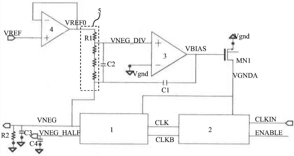
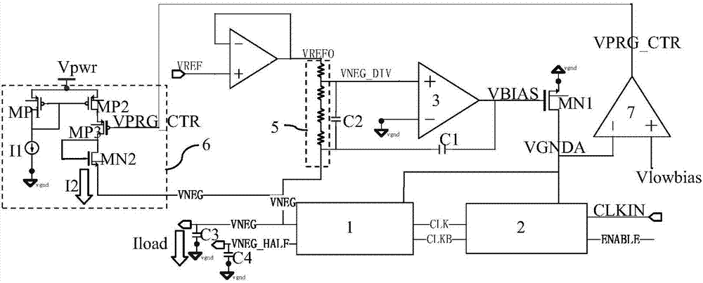
[0049] like figure 2 As shown, it is a schematic diagram of the negative pressure VNEG charge pump of the embodiment of the present invention. The negative pressure VNEG charge pump of the embodiment of the present invention includes:

[0050] A voltage divider circuit 5, the voltage divider circuit 5 is connected between the negative voltage VNEG output by the charge pump 1 and the first reference voltage VREF0, the voltage divider circuit 5 outputs the negative voltage VNEG and the first reference voltage VREF0 The divided voltage is used as the feedback voltage VNEG_DIV.

[0051] figure 2 In the shown structure, the voltage divider circuit 5 is composed of a first resistor string, figure 2 The first resistor string is formed by connecting multiple resistors R1 in series. In other embodiments, the voltage dividing circuit 5 is formed by connecting multiple MOS transistors in series, and the drains and gates of each MOS transistors are connected together.

[0052] The ...


PUM


Abstract

The invention discloses a negative-voltage charge pump. The negative-voltage charge pump comprises a voltage division circuit connected between the negative voltage output by the charge pump and a first reference voltage; the output partial voltage is used as a feedback voltage to be connected to the first input end of a first operational amplifier; the second input end of the first operational amplifier is grounded; the output end of the first operational amplifier is connected to the gate of a first NMOS transistor; the source of the first NMOS transistor is grounded; a drain outputs a clock control signal; the clock signal is input to the input end of the charge pump through a clock control circuit; the clock control signal is input to the clock control circuit to adjust the amplitude of the clock signal; a second comparator monitors the value of the clock control signal and enables a current path to be conducted to the first output end of the charge pump when the clock control signal is greater than the first bias voltage, thereby improving the total load current of the charge pump and lowering the clock control signal until the clock control circuit can correctly transmit the low-level value of the clock signal; and by virtue of the negative-voltage charge pump, the circuit stability can be improved.

Description

technical field [0001] The invention relates to a semiconductor integrated circuit, in particular to a negative charge pump (Negative charge pump). Background technique [0002] like figure 1 As shown, it is a schematic diagram of an existing negative pressure charge pump. The negative pressure charge pump in the embodiment of the present invention includes: [0003] A voltage divider circuit 5, the voltage divider circuit 5 is connected between the negative voltage VNEG output by the charge pump 1 and the first reference voltage VREF0, the voltage divider circuit 5 outputs the negative voltage VNEG and the first reference voltage VREF0 The divided voltage is used as the feedback voltage VNEG_DIV. The voltage divider circuit 5 is composed of a first resistor string, figure 2 The first resistor string is formed by connecting multiple resistors R1 in series. [0004] The first reference voltage VREF0 is output by a reference voltage regulating circuit. figure 1 Among the...

Claims


Application Information

Patent Timeline
IPC IPC(8): H02M3/07
CPCH02M3/07H02M3/071
Inventor 李祖渠刘芳芳
Owner SHANGHAI HUAHONG GRACE SEMICON MFG CORP
Features
  • R&D
  • Intellectual Property
  • Life Sciences
  • Materials
  • Tech Scout
  • Unparalleled Data Quality
  • Higher Quality Content
  • 60% Fewer Hallucinations
Learn More