Radio frequency switch circuit

A radio frequency switch and circuit technology, applied in the field of circuits, can solve the problems of long switching time, the contradiction between insertion loss and switching time, etc., to achieve the effect of improving radio frequency characteristics and optimizing the switching time of radio frequency switches

Active Publication Date: 2017-12-19
SHANGHAI HUAHONG GRACE SEMICON MFG CORP
View PDF4 Cites 6 Cited by
  • Summary
  • Abstract
  • Description
  • Claims
  • Application Information

AI Technical Summary

Problems solved by technology

When the switch is switched between off and on, it is actually a process of charging and discharging the gate and body capacitance of the control voltage through the bias resistor, so the time constant will become larger w

Method used


Image

  • Radio frequency switch circuit
  • Radio frequency switch circuit
  • Radio frequency switch circuit

Examples


Example Embodiment

[0023] The following describes the implementation of the present invention through specific specific examples in conjunction with the accompanying drawings. Those skilled in the art can easily understand other advantages and effects of the present invention from the content disclosed in this specification. The present invention can also be implemented or applied through other different specific examples, and various details in this specification can also be based on different viewpoints and applications, and various modifications and changes can be made without departing from the spirit of the present invention.

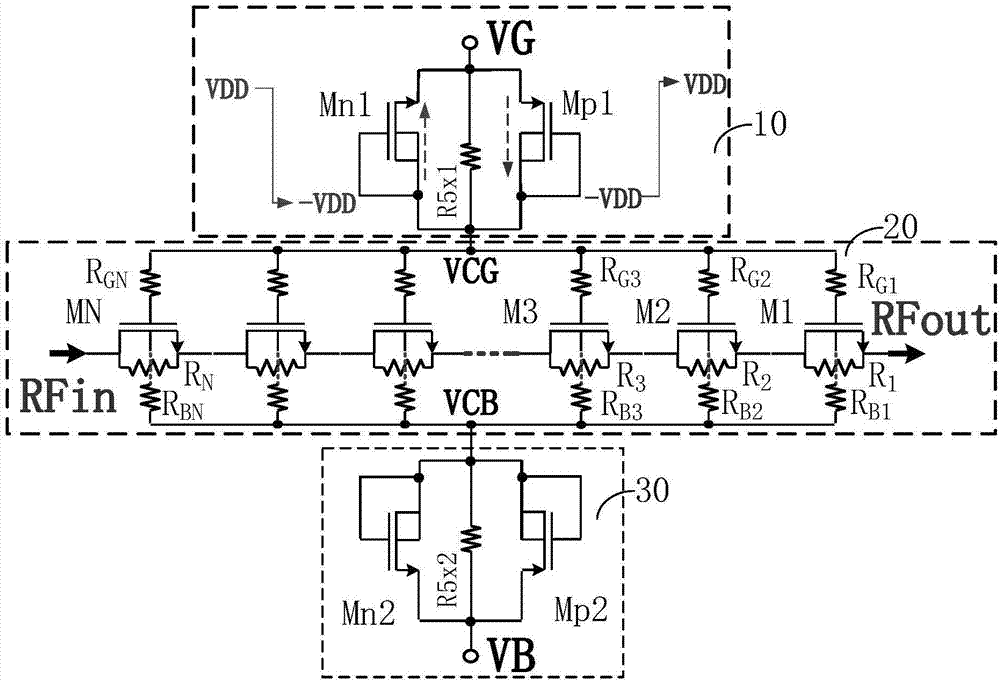
[0024] image 3 It is a circuit structure diagram of a radio frequency switch circuit of the present invention. Such as image 3 As shown, a radio frequency switch circuit of the present invention includes: the radio frequency switch circuit includes a gate voltage control module 10, a switch module 20, and a body voltage control module 30.

[0025] Among them, the gate v...


PUM


Abstract

The invention discloses a radio frequency switch circuit. The radio frequency switch circuit comprises a grid voltage control module for establishing the grid control voltage (VCG) for controlling on-off of a switch module, a body voltage control module for establishing the body control voltage (VCB) for controlling on-off the switch module and the switch module controlled by the grid control voltage (VCG) and the body control voltage (VCB) to connect or not connect a radio frequency input signal (RFin) to a radio frequency output end (RFout). The radio frequency switch circuit can optimize and reduce the on resistance (Ron) at a circuit layer and optimize the on-off time.

Description

technical field [0001] The invention relates to a circuit, in particular to a radio frequency switch circuit. Background technique [0002] figure 1 It is a schematic circuit diagram of a radio frequency switch circuit in the prior art. Such as figure 1 As shown, the radio frequency switch circuit in the prior art includes a switch module 10 and two common bias resistors, and the switch module 10 is composed of a plurality of cascaded NMOS transistors M1, M2, ..., MN, a plurality of body bias resistors R b , multiple gate bias resistors R g and a plurality of path resistors R, and common bias resistors Rx1 and Rx2 are connected between the switch module 10 and the gate control voltage VG and the body control voltage VB. [0003] The reduction of the on-resistance Ron of the switch module 10 is crucial to improving radio frequency characteristics such as insertion loss and harmonics of the radio frequency switch, and there is usually a certain gap between the on-resistanc...

Claims


Application Information

Patent Timeline
IPC IPC(8): H03K17/041
CPCH03K17/04106
Inventor 戴若凡
Owner SHANGHAI HUAHONG GRACE SEMICON MFG CORP
Why Eureka
Try Eureka