SMA connector

a technology of superplastic metal alloy and micro-wave, which is applied in the direction of waveguide type devices, multiple-port networks, coupling device connections, etc., can solve the problems of increasing production costs and complicated manufacturing processes, and achieves the reduction of rf loss, simple manufacturing process, and improved rf characteristics

Active Publication Date: 2006-06-15
KWANGWOON UNIV IND ACADEMIC COLLABORATION FOUND
View PDF1 Cites 2 Cited by
  • Summary
  • Abstract
  • Description
  • Claims
  • Application Information

AI Technical Summary

Benefits of technology

[0009] It is other object of the present invention to provide a technique to simplify the manufacturing process and to improve RF characteristics by a fastening method using the inserted slit for reduction of RF loss caused by the discontinuity at the outer conductor.
[0010] It is other object of the present invention to provide a microwave SMA connector in order that PTFE dielectric substance coincides with the outer connector for impedance matching according to the technology operating at the higher frequency by using the connector outer conductor having step structure and by improving the dielectric loss by inserting air layer through the separation of the dielectric substance to get the same characteristics as at low frequency.
[0011] It is other object of the present invention to provide a technique to simplify the manufacturing process and improve RF characteristics by a fastening method using the central conductor's diameter change according to the impedance matching between dielectric substance and air layer.

Problems solved by technology

And also a fastening method according to the epoxy insertion among the methods used in a microwave connector is used and it is a method, which makes holes at the side of a connector to insert epoxy and the conductor's thickness should be different for impedance junction and the manufacturing process is becoming complicated more and more and induces the production cost's increase as well as many difficulties in designing microwave SMA connector.

Method used


Image

  • SMA connector
  • SMA connector
  • SMA connector

Examples


Embodiment Construction

[0026]

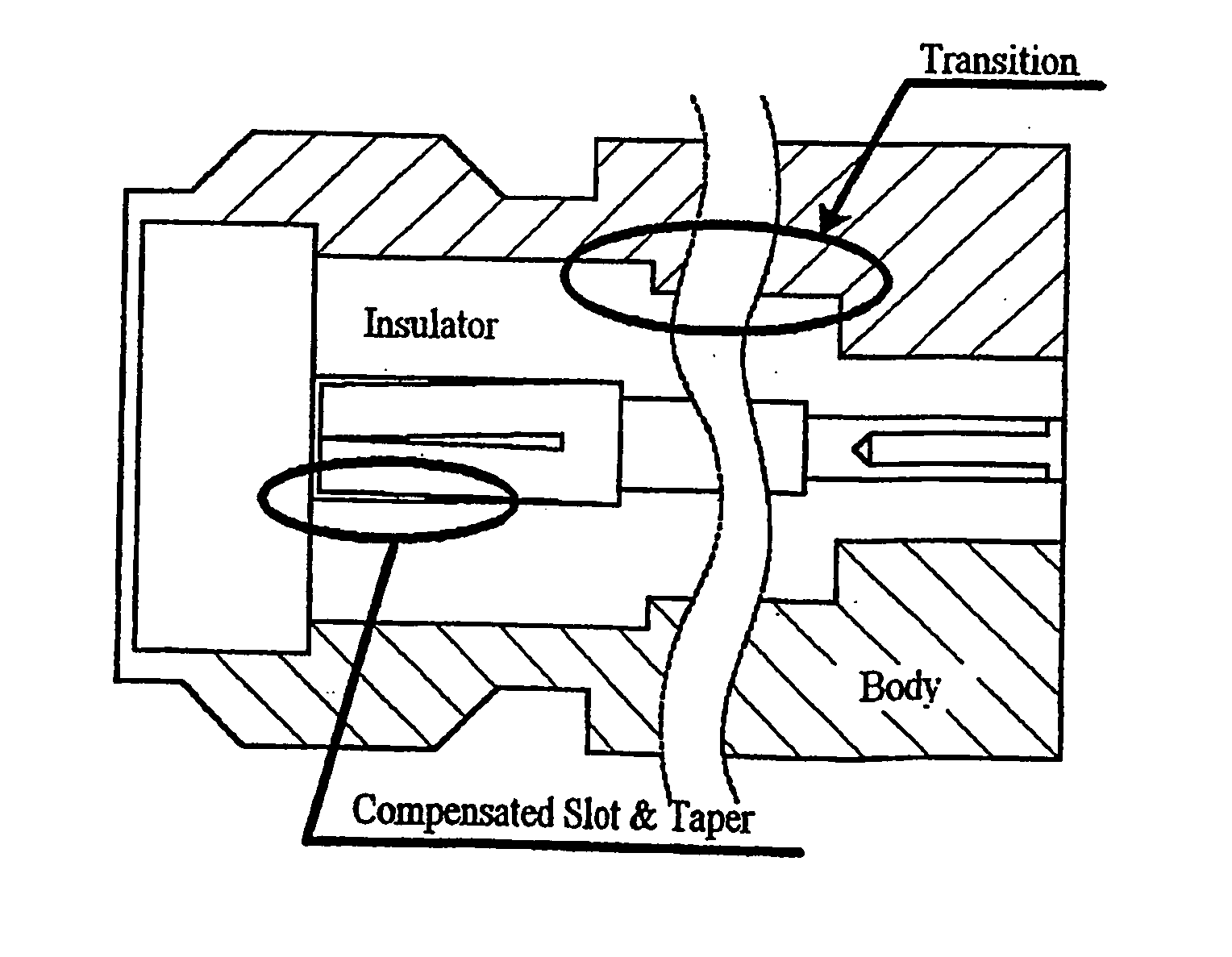
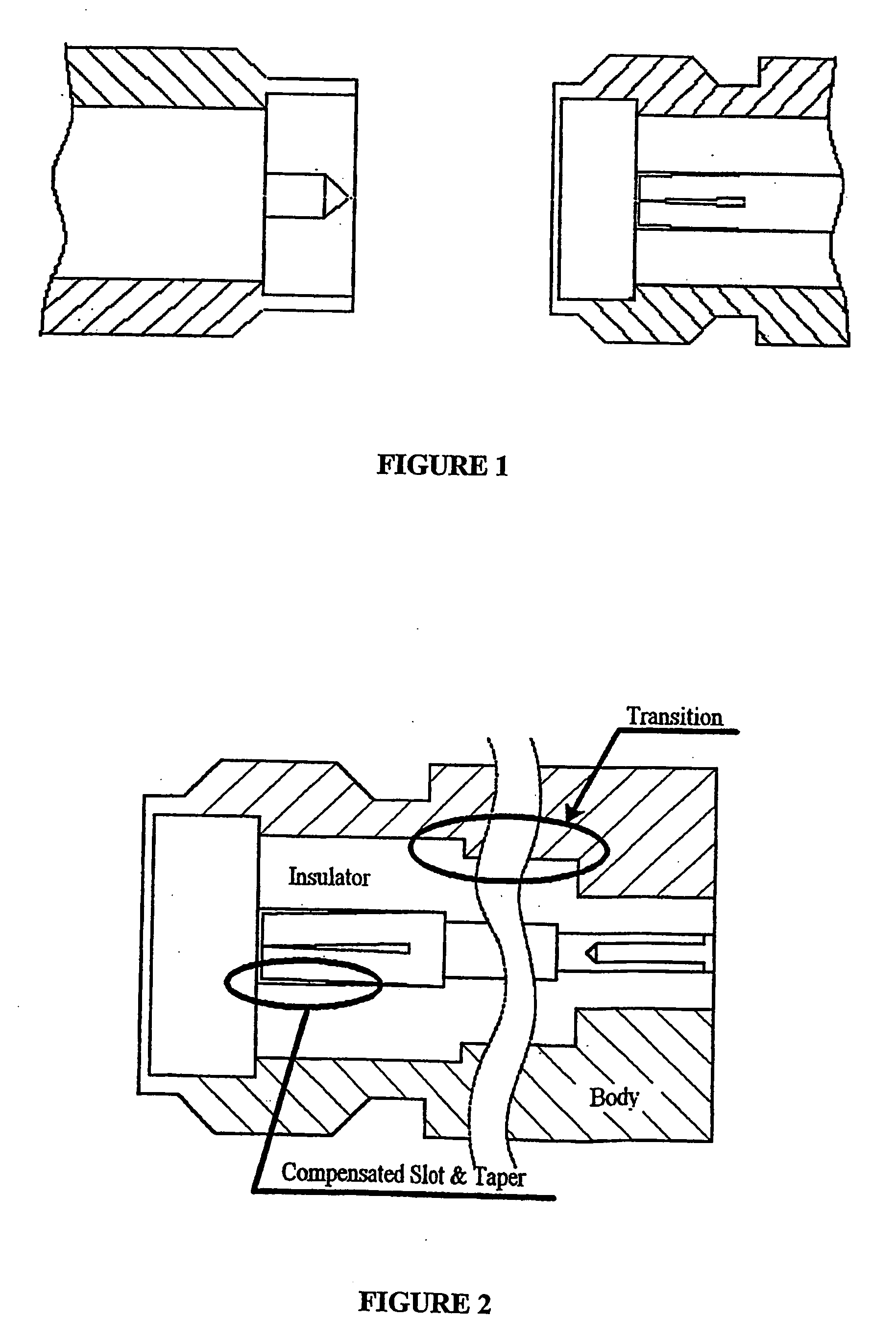
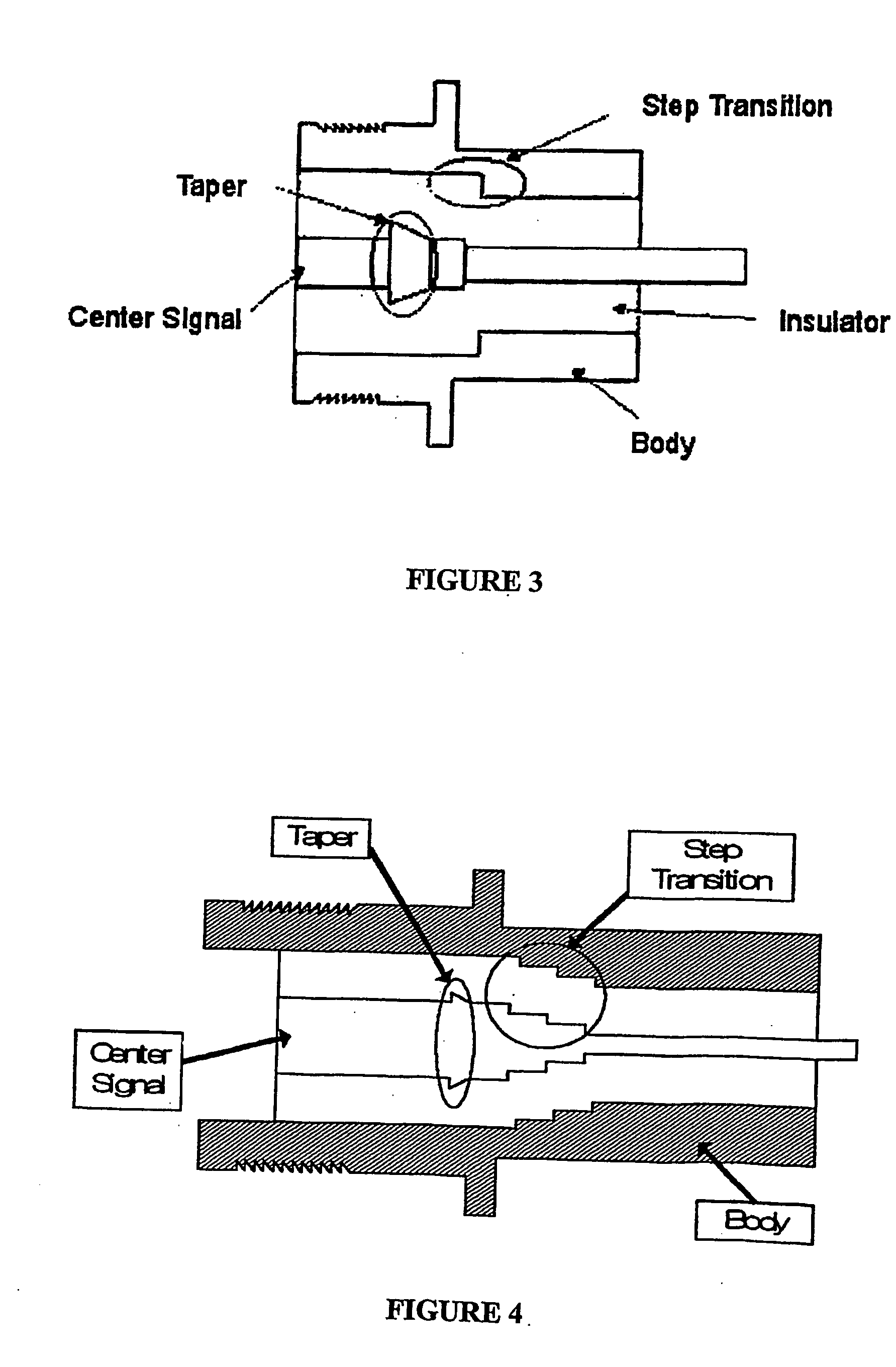
[0027] Hereinafter we explain about a microwave SMA connector having improved RF characteristics according to the present invention with reference to FIG. 3, which shows a preferred embodiment of the present invention.

[0028] In accordance with the present invention, the characteristic impedance of a microwave SMA connector having improved RF characteristics is obtained by the ratio of the thickness of central conductor i.e. by the ratio of central signal line to the thickness of insulator.

[0029] Therefore it is preferable that characteristic impedance of the connector is designed to be 50Ω. It is preferable that the insulator is Teflon and the body and the central conductor are gilded with gold in order to optimize the RF characteristics of the conductor. The body of the connector designed according to the invention plays a role as ground from the RF characteristics point of view.

[0030] In addition, taper fixes dielectric substance i.e. insulator to central conductor and it...


PUM


Abstract

The present invention discloses to an SMA connector, a preferable embodiment of which comprises a body acting as ground, a central conductor existing in the inner part of the ground, an insulator with a predetermined dielectric constant existing between the body and the central conductor, a first step transition part formed in the body, a taper formed in the central conductor in order to improve RF characteristics and to fix the central conductor and the insulator, and a second step transition part formed in the central conductor corresponding to the first step transition part to improve RF characteristics.

Description

FIELD OF THE INVENTION [0001] This invention relates to a microwave SMA (superplastic metal alloy) connector. PRIOR ART OF THE INVENTION [0002] Recently, owing to the development of communication technology and expansion of communication market, the common frequency bandwidth is using high frequencies more and more. For example, wireless LAN is used at 5.8 GHz and LMDS (Local Multipoint Distribution Service) is used at 24˜25 GHz of K-band, where LMDS is a technique for replacing the existing cable CATV by wireless CATV. In addition, X-band (812.5 GHz) and Ku-band (12.5˜18 GHz), which are used to satellite communication, are appearing nowadays. Accordingly the countries centering on USA, Japan, Europe put spurs to the development of goods that used in high frequency bandwidth. Like this, the development of RF connector becomes important gradually according to the fact that the common frequency bandwidth is becoming higher. While in the existing RF connector production is convenient a...

Claims


Application Information

Patent Timeline
Patent Type & Authority Applications(United States)
IPC IPC(8): H01R9/05H01P1/04H01R13/646
CPCH01P1/045H01R24/44H01R24/52H01R2103/00
Inventor LEE, JONG-CHULLEE, JAE-SUNKIM, KI-BYOUNGYUN, TAE-SOONLEE, SANG-GUNKIM, NAM-YOUNGKIM, JONG-HEONLEE, BYUNG-JEYUN, BUB-SANGRA, KUK-HWANLEE, YOUN-JOOHONG, SUN-WON
Owner KWANGWOON UNIV IND ACADEMIC COLLABORATION FOUND
Why Eureka
Try Eureka