Radio frequency testing switch of flowing terminal

A radio frequency test and terminal technology, applied in electrical switches, parts of connecting devices, contact parts, etc., can solve problems such as reduced electrical conductivity and corrosion of outer casings

Inactive Publication Date: 2006-07-26
德菱机电有限公司
View PDF0 Cites 2 Cited by
  • Summary
  • Abstract
  • Description
  • Claims
  • Application Information

AI Technical Summary

Problems solved by technology

[0018] In addition, because the gold plating on the traditional outer casing is extremely thin, the outer casing is easily corroded due to oxidation, and the conductive performance is thus reduced

Method used


Image

  • Radio frequency testing switch of flowing terminal
  • Radio frequency testing switch of flowing terminal
  • Radio frequency testing switch of flowing terminal

Examples


Embodiment Construction

[0044] The following combination Figure 5 to Figure 8 The present invention is described in detail with specific examples:

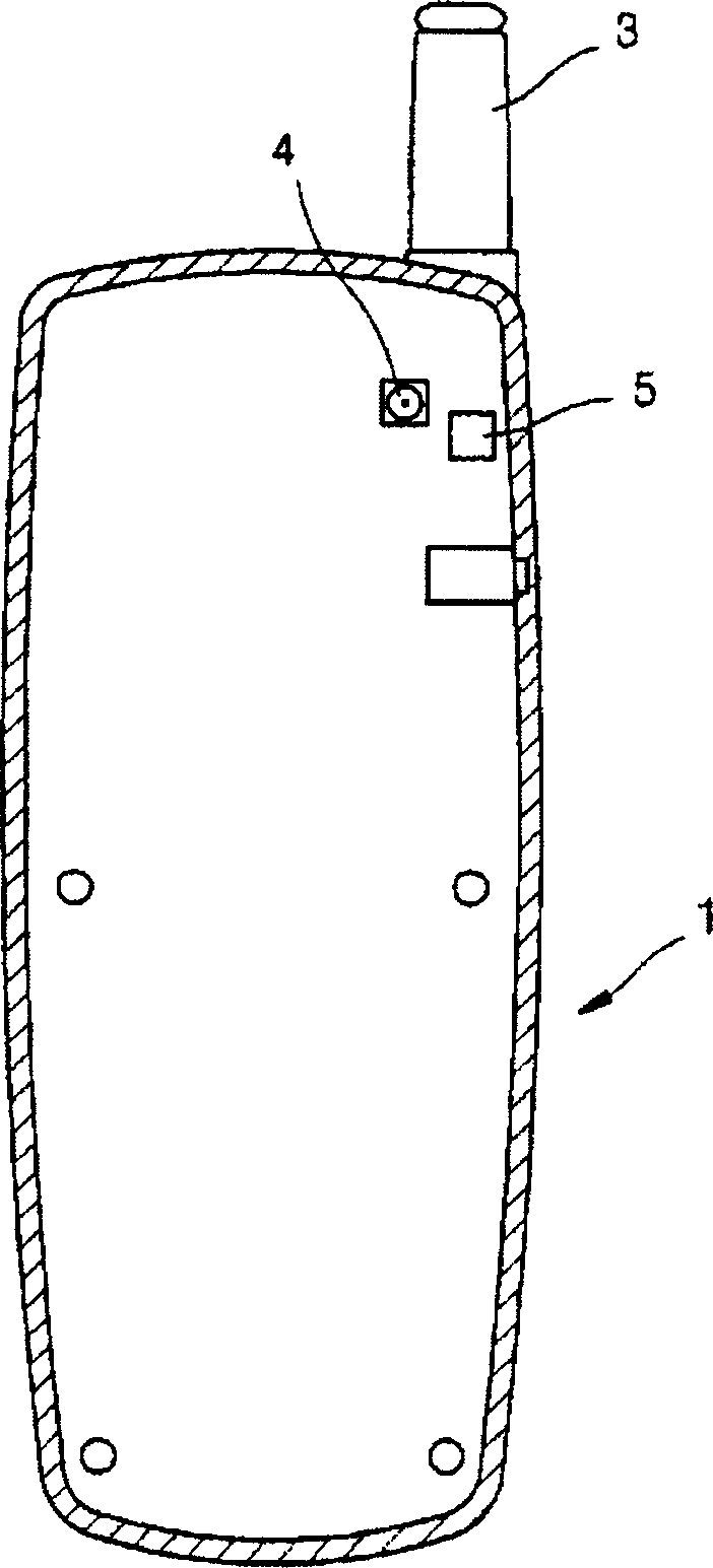
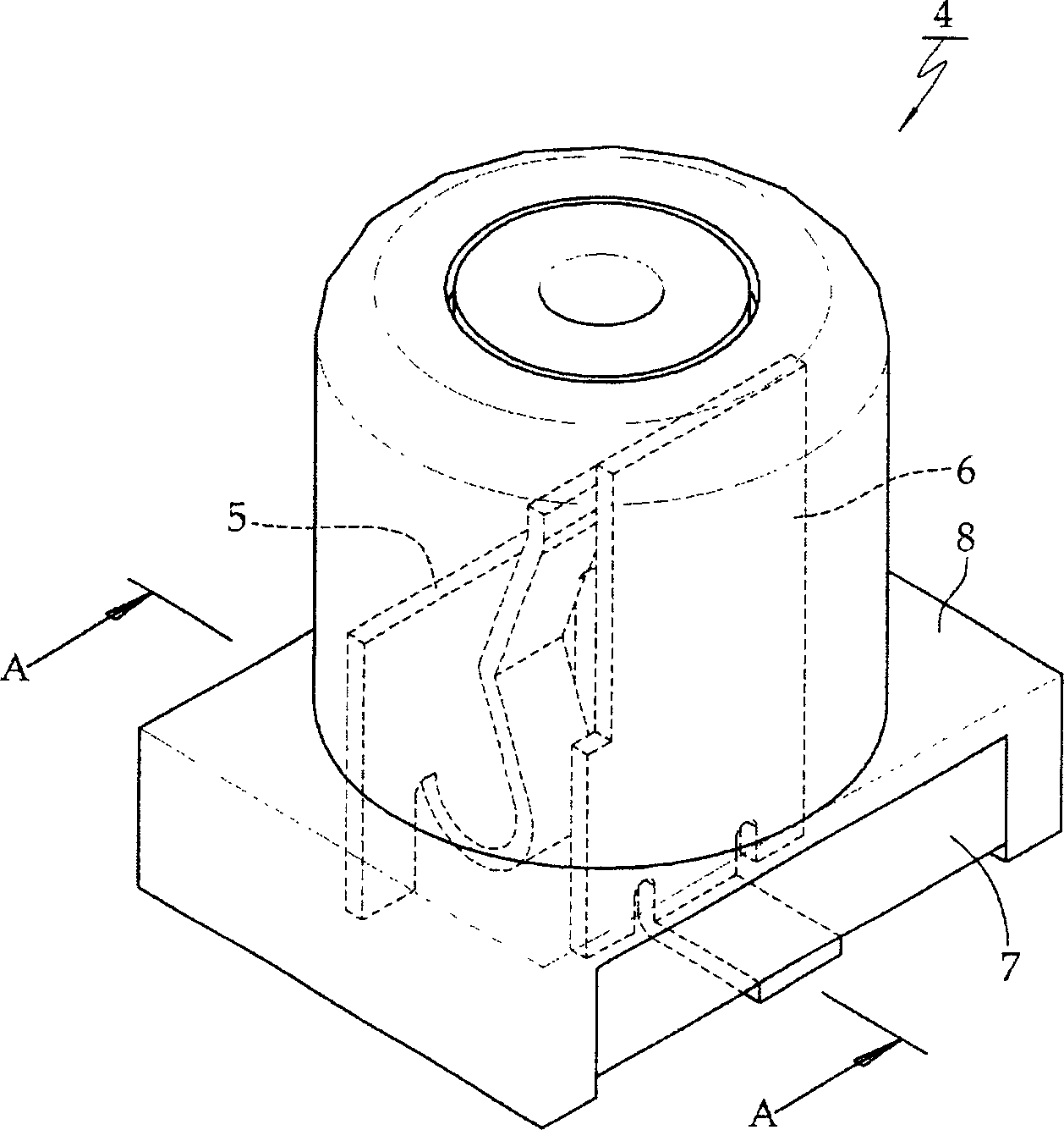
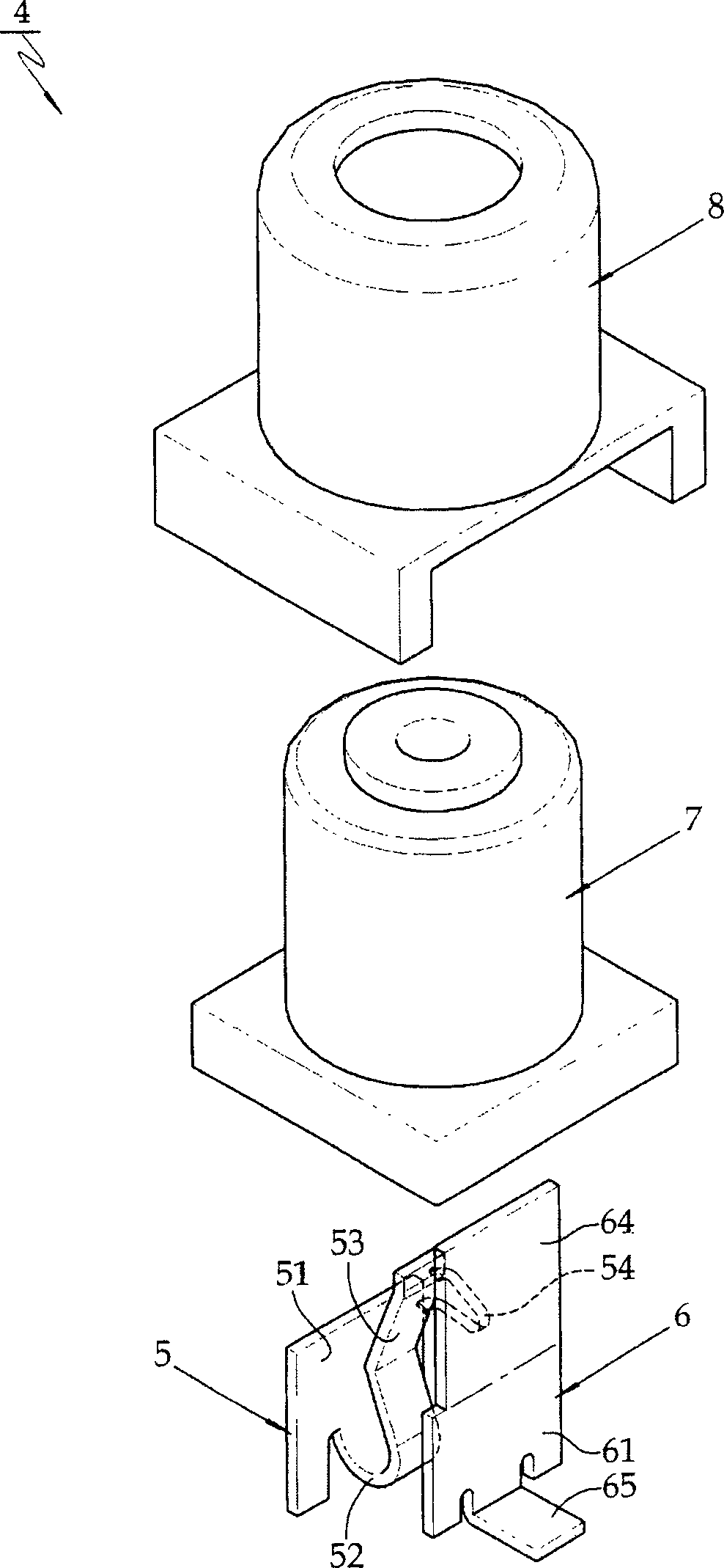
[0045] As shown in the figure, the radio frequency test switch 1000 of the mobile terminal of the present invention includes a first terminal 500, a second terminal 600, a housing 700 for accommodating the first terminal 500 and the second terminal 600, and a An outer casing 800 surrounding the casing 700 .

[0046] The first terminal 500 includes a first vertical plate 510, an elastic support block 520 bent at the lower half of the first vertical plate 510, and a connecting port bent upward from the elastic support block 520 into a zigzag joint part 530 , a first joint block 540 extending forward from the port joint part 530 , and a first support plate 550 bent backward at the lower end of the first vertical plate 510 .

[0047] In addition, the second terminal 600 includes a second vertical plate 610 , a second support plate 650 extending laterally ...


PUM


Abstract

The invention discloses a flowing terminal radio frequency testing switch, including a first terminal (500), a second terminal (600), a casing (700) which is used for containing the first terminal (500) and the second terminal (600) and an outer casing (800) around the casing (700). The flowing terminal radio frequency testing switch is characterized in that the first terminal (500) includes a first vertical slab (510), an elastic backing block (520) which is inflected at the lower half part of the first vertical slab (510), a connecting port joining component (530) which is formed by inflecting the elastic backing block (520) upwardly to be zigzag, a first joining block (540) which is formed by extending forward from the connecting port joining component (530) and a first support plate (550) which is inflected backward at the end of the lower part of the first vertical slab (510); the second terminal (600) includes a second vertical slab (610), a second support plate (650) which is extended laterally from the second vertical slab (610), and a second joining block (640) which is extended upwardly from the end of the upper part of the second vertical slab (610); the thickness of the first terminal (500) is 0.1mm to 0.12mm; the width of the elastic backing block (520) is 0.5mm to 0.6mm; the total height after the combination of the first terminal (500), the second terminal (600), the casing (700) and the outer casing (800) is 2.45mm to 2.5mm; one edge of the end of the upper part of the second joining block (640) of the second terminal (600) is a chamfered edge; the width of the second joining block (640) is 0.4mm to 0.5mm; the surface of the outer casing (800) is formed by firstly coating a nickel coating (910) which is made from sulfamic acid and 1micron to 2 microns thick and a gold coating (920) which is 0.08 micron to 0.2 micron thick in turn and then being pressed.

Description

technical field [0001] The present invention relates to a radio frequency test switch for a mobile terminal, in particular to a radio frequency test switch capable of testing whether the radio frequency sent from a mobile terminal and transmitted by a radio frequency transmission and receiving part for wireless communication is sufficient for the mobile terminal to operate . Background technique [0002] Generally speaking, a mobile terminal transmits and receives radio frequency signals through an antenna to communicate with another party wirelessly, that is, general wireless communication can only be achieved when the radio frequency is transmitted according to established standards. Therefore, in the final stage of the process of producing mobile terminals, it is necessary to check the radio frequency transmission and reception conditions. [0003] figure 1 Shows the rear of a conventional mobile terminal. [0004] As shown in the figure, the rear structure of a mobile...

Claims


Application Information

Patent Timeline
Patent Type & Authority Applications(China)
IPC IPC(8): H01H27/00H01R13/71H01R13/11
CPCH01H13/04H01H13/14H01H13/26
Inventor 高光培白周荣
Owner 德菱机电有限公司
Why Eureka
Try Eureka