Unmanned aerial vehicle charging system and charging method based on lasers

A charging system and unmanned aerial vehicle technology, applied in charging stations, electric vehicle charging technology, motor vehicles, etc., can solve the problems of difficulty in ensuring normal laser incidence conditions, large laser angle depletion coefficient, low energy transmission efficiency, etc. The effect of energy utilization, improving energy transmission efficiency, and avoiding energy waste

Pending Publication Date: 2017-12-22
BEIFANG UNIV OF NATITIES
View PDF7 Cites 11 Cited by
  • Summary
  • Abstract
  • Description
  • Claims
  • Application Information

AI Technical Summary

Problems solved by technology

As far as the current laser charging technology is concerned, there are still technical problems that need to be solved urgently, such as the large depletion coefficient of the laser angle, it is difficult to ensure the normal incident condition of the laser, which makes the energy transmission efficiency low, resulting in a large amount of energy loss

Method used


Image

  • Unmanned aerial vehicle charging system and charging method based on lasers
  • Unmanned aerial vehicle charging system and charging method based on lasers
  • Unmanned aerial vehicle charging system and charging method based on lasers

Examples


Embodiment 1

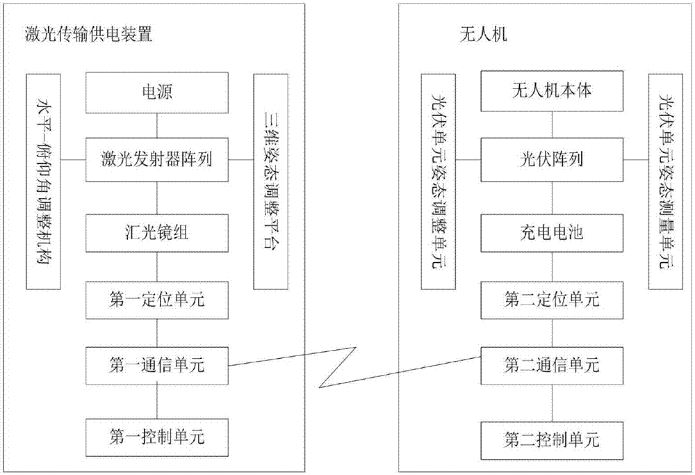
[0051] see figure 1 , the laser-based drone charging system provided in this embodiment includes a laser transmission power supply device and a drone, and the laser transmission power supply device includes a power supply, a laser transmitter array, a first positioning unit, a first communication unit, The first control unit and the horizontal-pitch angle adjustment mechanism, the drone includes a drone, a photovoltaic array, a rechargeable battery, a second positioning unit, a second communication unit, a photovoltaic unit attitude adjustment unit, a photovoltaic unit attitude measurement unit and Second control unit.

[0052] The power supply provides electrical energy for the laser array, and the laser beam emitted by the laser emitter array is incident on the photovoltaic array. The photovoltaic array converts the parallel laser beam into electrical energy to charge the rechargeable battery, and the rechargeable battery provides the electrical energy required for the drone...

Embodiment 2

[0073] see Figure 6-7 , compared with Embodiment 1, the laser-based unmanned aerial vehicle charging system provided in this embodiment also includes a light-collecting unit. The output scattered laser light is reflected by the light-collecting mirror group to form a parallel laser beam output. The converging mirror group enables the emitted laser to form a parallel laser beam after multiple reflections, which can enhance the converging effect of the emitted laser.

[0074] like Image 6 As shown, the light converging mirror group includes an outer cone mirror and an inner cone mirror. The laser light emitted by the laser emitter array is incident on the outer cone mirror and then reflected to the inner cone mirror. After being reflected by the inner cone mirror, a parallel laser beam is formed. It should be noted that the outer cone mirror and the inner cone mirror are both cone mirrors. In order to indicate the distinction, they are named respectively by the arrangement o...


PUM


Abstract

The invention relates to an unmanned aerial vehicle charging system and charging method based on lasers. The charging system comprises a laser transmission power supply device and an unmanned aerial vehicle, the laser transmission power supply device comprises a power supply, a laser transmitter unit, a first positioning unit, a first communication unit and a horizontal-pitch angle adjustment mechanism, and the unmanned aerial vehicle comprises an unmanned aerial vehicle body, a photovoltaic unit, a rechargeable battery, a second positioning unit, a second communication unit, a photovoltaic unit attitude adjustment unit and a second control unit; according to the charging system, the two positioning units collect position information of the laser transmission power supply device and position information of the unmanned aerial vehicle respectively, the photovoltaic unit is adjusted to be perpendicular to incident laser beams through the photovoltaic unit attitude adjustment unit, the energy transmission efficiency is improved, and the energy loss is reduced.

Description

technical field [0001] The invention relates to the technical field of charging, in particular to a laser-based unmanned aerial vehicle charging system and charging method. Background technique [0002] As a kind of unmanned aircraft mainly controlled by radio remote control or by its own program, compared with manned aircraft, UAV has the advantages of small size, low cost, convenient use, low requirements for combat environment, and high battlefield survivability. Strong and other advantages, it is favored by armies all over the world. However, short battery life is one of the main disadvantages of drones. [0003] In the prior art, solar energy and microwave-based wireless energy transmission technology are usually used to charge the onboard energy storage battery, but solar energy technology is affected by weather conditions and cannot be used at night; microwave-based wireless energy transmission technology uses electromagnetic induction of coils The conversion effici...

Claims


Application Information

Patent Timeline
Patent Type & Authority Applications(China)
IPC IPC(8): B60L11/18H02J50/30H02J50/90
CPCH02J50/30H02J50/90B60L53/00B60L2200/10Y02T90/16Y02T10/70Y02T10/7072Y02T90/14
Inventor 张白毛建东
Owner BEIFANG UNIV OF NATITIES
Why Eureka
Try Eureka