Automatic capping machine

A capping machine and capping technology, applied in packaging and other fields, can solve problems such as low production efficiency, low degree of automation, and complex structure, and achieve the effects of improving efficiency, high degree of automation, and reducing production costs

Inactive Publication Date: 2017-12-22
FOSHAN UNIVERSITY
View PDF7 Cites 4 Cited by
  • Summary
  • Abstract
  • Description
  • Claims
  • Application Information

AI Technical Summary

Problems solved by technology

However, the capping machines currently on the market usually use a lifting drive device to control the capping head to seal the cup cap. The lifting drive device has an up and down movement stroke. Such a packaging method has low production efficiency, complex structure, and low degree of automation. Therefore, it is necessary to develop a capping machine with simple structure, high capping efficiency and high degree of automation

Method used


Image

  • Automatic capping machine
  • Automatic capping machine
  • Automatic capping machine

Examples


Embodiment 1

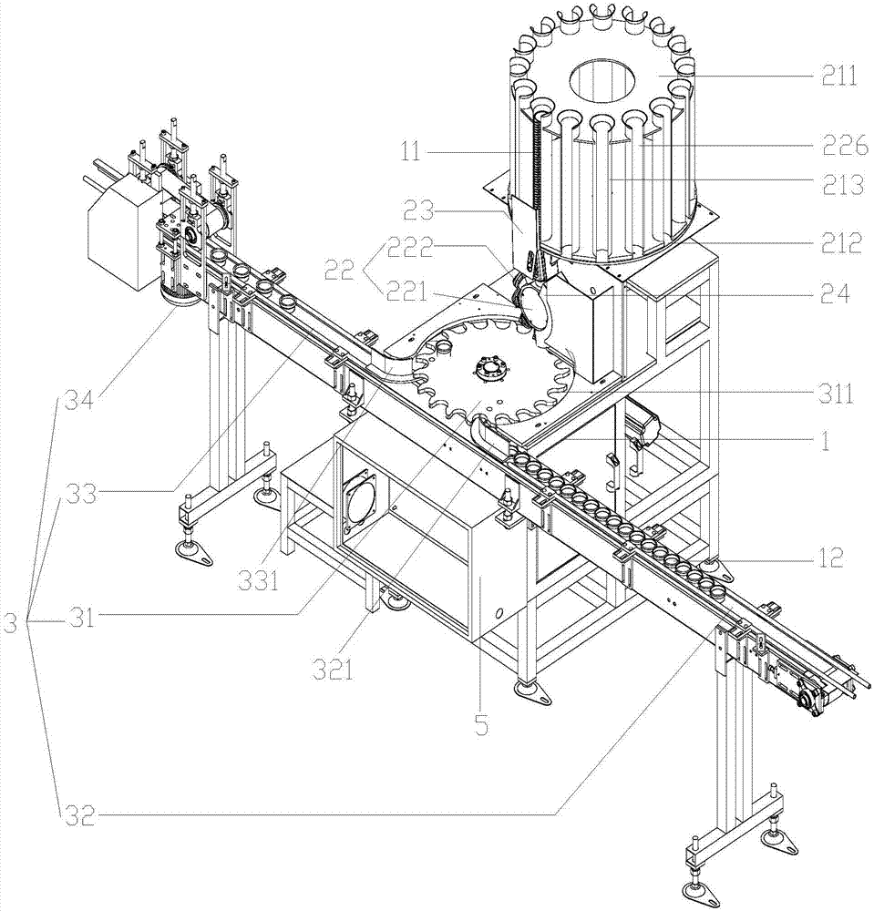
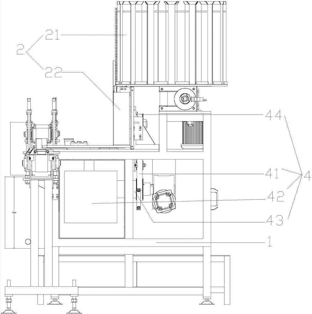
[0059] Such as Figure 1-5 As shown, an automatic capping machine includes: a workbench 1 on which a cap placing module 2 and a transmission module 3 for transporting a cup body 23 are arranged;

[0060] The cover-putting module 2 includes: a cover storage device 21, which rotates around a horizontal axis and is used to capture the cup cover 11 in the cover storage device 21 and press-fit the cup cover 11 on the cup body 12 device 22;

[0061] The capping device 22 is arranged below the cap storage device 21;

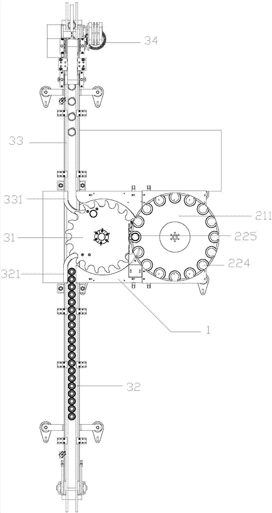
[0062] The transmission module 3 includes: a cup transport tray 31 rotating around a vertical axis, used to transport the uncapped cup body 12 to the first transmission track 32 of the cup transport tray 31, for receiving the transport cup The second transmission track 33 of the capped cup body 12 on the disc 31 is used to drive the transmission motor 34 of the first transmission track 32 and the second transmission track 33;

[0063] The capping device 22 is arrange...


PUM


Abstract

The invention discloses an automatic capping machine. The automatic capping machine comprises a worktable; the worktable is provided with a lid placing module and a transmission module used for conveying cup bodies; the lid placing module comprises a lid storing device and a capping device, wherein the capping device rotates around a horizontal axis and is used for obtaining cup lids in a sleeving mode and pressing the cup lids on the cup bodies; the capping device is arranged below the lid storing device; the transmission module comprises a cup conveying disc, a first transmission track and a second transmission track, wherein the cup conveying disc rotates around a vertical axis, the first transmission track is used for conveying the cup bodies to the cup conveying disc, and the second transmission track is used for receiving the capped cup bodies on the cup conveying disc; the capping device is arranged above the cup conveying disc; a driving module which is used for driving the capping device and the cup conveying disc to rotate is further arranged in the worktable; and the worktable is further provided with a controlling module. The automatic capping machine is simple in structure, high in capping efficiency and high in automation degree, and production cost is reduced.

Description

technical field [0001] The invention relates to a capping machine, in particular to an automatic capping machine. Background technique [0002] The capping machine is used to seal the cup lid on the filled cup to facilitate the transportation and sale of the product, and the capped product has good moisture-proof, mildew-proof, and anti-counterfeiting effects, which can prolong the storage period of the protected product . However, the capping machines currently on the market usually use a lifting drive device to control the capping head to seal the cup lid. The lifting drive device has an up and down movement stroke. Such a packaging method has low production efficiency, complex structure, and low degree of automation. Therefore, it is necessary to develop a capping machine with simple structure, high capping efficiency and high degree of automation. Contents of the invention [0003] The object of the present invention is to provide an automatic capping machine, which ...

Claims


Application Information

Patent Timeline
Patent Type & Authority Applications(China)
IPC IPC(8): B65B7/28
Inventor 方新国肖凯华寿庆
Owner FOSHAN UNIVERSITY
Why Eureka
Try Eureka