Charge transfer RC relaxation oscillator

A relaxation oscillator and charge transfer technology, applied in electrical components, electrical pulse generation, pulse generation, etc., can solve problems such as comparator delay time variation and oscillator frequency instability

Active Publication Date: 2017-12-22
NORTHWESTERN POLYTECHNICAL UNIV
View PDF2 Cites 7 Cited by
  • Summary
  • Abstract
  • Description
  • Claims
  • Application Information

AI Technical Summary

Problems solved by technology

The RC relaxation oscillator has the following disadvantages: the offset and delay time of the comparat...

Method used


Image

  • Charge transfer RC relaxation oscillator
  • Charge transfer RC relaxation oscillator
  • Charge transfer RC relaxation oscillator

Examples


specific Embodiment

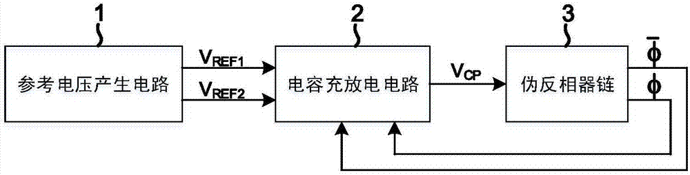
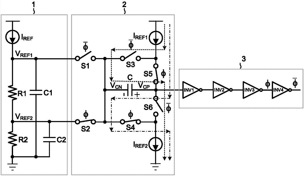
[0037] refer to Figure 4 . The RC relaxation oscillator circuit is composed of a reference voltage generating circuit 1, a capacitor charging and discharging circuit 2 and a pseudo-inverter chain 3.

[0038] The reference voltage generating circuit 1 is composed of a current mirror circuit, a resistor R1, a resistor R2, a capacitor C1 and a capacitor C2. Wherein, the current mirror circuit is composed of PMOS transistor M1 and PMOS transistor M2. The gates of the PMOS transistors M1 and M2 are connected to form a current mirror structure; their sources are connected to a power supply. Resistor R1 is connected in series with resistor R2, and one end of resistor R1 is connected to drain V of PMOS transistor M2 REF2 Connected, the other end of the resistor R1 and one end of the resistor R2 V REF1 connected, and the other end of resistor R1 is connected to ground. One end of the capacitor C1 and the drain V of the PMOS transistor M2 REF2 The other end of capacitor C1 is con...


PUM


Abstract

The invention relates to a charge transfer RC relaxation oscillator applied to low power consumption equipment. Compared with a relaxation oscillator circuit structure in the background technology, the charge transfer RC relaxation oscillator uses a pseudo inverter chain to replace a comparator so as to avoid the influence of imbalance and time-delay of the comparator on the clock frequency, following changes of technology, voltage and temperature. At the same time, the frequency of the oscillator is irrelevant to the charge and discharge current and the threshold of the pseudo inverter chain. In the charge transfer RC relaxation oscillator, traditional capacitor cathode grounding is changed as connection with two reference voltages alternately, the charge transfer RC relaxation oscillator utilizes the charge transfer mode to generate a triangular wave signal with a step voltage on the anode of the capacitor so as to be able to use a pseudo inverter to determine the magnitude of the level of the signal. The charge transfer RC relaxation oscillator provides a pseudo inverter chain structure which has no short circuit current, wherein the time delay does not change following power voltage, and the time delay of the inverter chain can be realized through adjustment of resistance value.

Description

technical field [0001] The invention belongs to the technical field of electronic circuits, in particular to an RC relaxation oscillator circuit. Background technique [0002] Oscillators are widely used in low-power on-chip integrated systems such as energy harvesting systems, microcontrollers, and high-speed interface circuits. In these applications, area and power consumption are two key considerations. For example, in low-power energy harvesting systems, the energy harvested by the system is very limited, and there are strict constraints on the power consumption of the clock circuit. The RC relaxation oscillator has the characteristics of low power consumption and easy on-chip integration, and is very suitable for application in these low-power electronic devices. [0003] refer to Figure 5 . The document "S.L.J.Gierkink and E.van Tuij, A coupled sawtoothoscillator combining low jitter with high control linearity[J], IEEE Journal of Solid-State Circuits, vol.37, no.6...

Claims


Application Information

Patent Timeline
IPC IPC(8): H03K3/0231H03K3/011H03K4/50
Inventor 马彦昭崔楷张盛兵樊晓桠
Owner NORTHWESTERN POLYTECHNICAL UNIV
Why Eureka
Try Eureka