
A Distributed Photoelectric Hybrid Switch Structure

An optoelectronic hybrid and switching structure technology, applied in the field of satellite communications, can solve the problems of low scalability, poor optical/electrical business ratio flexibility, and high engineering complexity, achieving high throughput, easy modularization and productization Design, the effect of reducing complexity

Active Publication Date: 2020-06-09
XIAN INSTITUE OF SPACE RADIO TECH
View PDF5 Cites 0 Cited by
  • Summary
  • Abstract
  • Description
  • Claims
  • Application Information

AI Technical Summary

Problems solved by technology

[0004] The technical problem solved by the present invention is: to overcome the deficiencies of the prior art, to provide a distributed photoelectric hybrid switching structure, and to solve the problem of low scalability of the existing structure, poor flexibility of optical / electrical service ratio and high complexity of engineering implementation By changing the number and combination of the basic units of photoelectric / electrical-optical switching, the expansion of switching scale and the flexible ratio of optical / electrical services can be realized, so as to adapt to the access requirements of optical switching / electrical switching in different systems, and facilitate modularization and product design.

Method used


Image

  • A Distributed Photoelectric Hybrid Switch Structure
  • A Distributed Photoelectric Hybrid Switch Structure
  • A Distributed Photoelectric Hybrid Switch Structure

Examples


Embodiment Construction

[0020] Below in conjunction with accompanying drawing, the present invention is described in further detail:

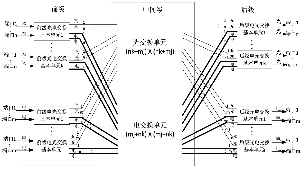
[0021] figure 1 It is a block diagram of the distributed photoelectric hybrid switching structure of the present invention. Such as figure 1 As shown, the distributed photoelectric hybrid switching structure includes: a front-level switching unit, an intermediate-level switching unit, and a rear-level switching unit; wherein,

[0022] The pre-stage switching unit includes k pre-stage photoelectric switching basic units and j pre-stage electro-optical switching basic units;

[0023] The intermediate switching unit includes an optical switching unit and an electrical switching unit;

[0024] The post-stage switching unit includes k post-stage electro-optical exchange basic units and j post-stage photoelectric exchange basic units;

[0025] The input of each front-level photoelectric switching basic unit is an optical signal, and the output is an optical signal and a...


PUM


Abstract

The invention discloses a distributed photoelectric hybrid switching structure, comprising a fore-stage switching unit, an intermediate-stage switching unit and a post-stage switching unit, wherein the fore-stage switching unit comprises k fore-stage photoelectric switching basic units and j fore-stage electro-optical switching basic units; the intermediate-stage switching unit comprises an optical switching unit and an electrical switching unit; and the post-stage switching unit comprises k post-stage electro-optical switching basic units and j post-stage photoelectric switching basic units. According to the distributed photoelectric hybrid switching structure disclosed by the invention, the problem that an existing structure is low in scalability, poor in optical / electrical service ratio flexibility and high in project realization complexity can be solved, the expansion of switching scales and the flexible proportioning of optical / electrical services can be separately realized by changing and combining the number of the photoelectric / electro-optical switching basic units, the access requirements of optical switching / electrical switching in different systems can be adapted, and the modular and product design can be facilitated.

Description

technical field [0001] The invention belongs to the technical field of satellite communication, and in particular relates to a distributed photoelectric hybrid switching structure. Background technique [0002] In the future, space-based information network space nodes need to adapt to different link types such as microwaves and lasers, different information carrying methods such as optical and electrical, and information exchange requirements of different granularities. [0003] In the existing photoelectric switching method, the ground network carries out backbone transmission through optical fiber, the switching method adopts electronically controlled optical switching or electrical switching, the optical switching structure adopts a single optical switch switching matrix or wavelength switching array, and the electrical switching structure adopts a store-and-forward structure. This switching structure and method cannot be adapted to both microwave and laser data links at...

Claims


Application Information

Patent Timeline
Patent Type & Authority Patents(China)
IPC IPC(8): H04Q11/00H04B10/27
CPCH04B10/27H04Q11/0005H04Q11/0062H04Q2011/0026H04Q2011/0073
Inventor 崔涛周诠黎军梁薇呼延烺张怡李静玲刘娟妮
Owner XIAN INSTITUE OF SPACE RADIO TECH
Learn More