Piezoelectric ultrasonic transducer and preparation method thereof

A piezoelectric ultrasonic and transducer technology, applied in the field of ultrasonic sensors, can solve the problems of large influence of parasitic capacitance, low output impedance, low driving voltage, etc.

Active Publication Date: 2017-12-26
AAC TECH PTE LTD
View PDF3 Cites 4 Cited by
  • Summary
  • Abstract
  • Description
  • Claims
  • Application Information

AI Technical Summary

Problems solved by technology

[0003] The current MEMS ultrasonic transducers are mainly capacitive and piezoelectric. Among them, the MEMS capacitive ultrasonic transducer is composed of two upper and lower electrode plates, driven by the electrostatic force between the electrode plates, and has a large electromechanical coupling coefficient. , high resonant frequency, but there are also disadvantages such as high driving voltage, greater influence by parasitic capacitance, large electrical output impedance, difficult to match, difficult to balance receiving efficiency and transmitting efficiency; compared with capacitive ultrasonic transducers , the piezoelectric ultrasonic transducer is composed of a piezoelectric layer, a vibrating layer, and upper and lower metal electrodes. It has the advantages of low driving voltage, low output impedance, and both transmission and reception efficiency, so it has been applied in many occasions.

Method used


Image

  • Piezoelectric ultrasonic transducer and preparation method thereof
  • Piezoelectric ultrasonic transducer and preparation method thereof
  • Piezoelectric ultrasonic transducer and preparation method thereof

Examples


Embodiment Construction

[0025] The present invention will be further described below in conjunction with the accompanying drawings and embodiments.

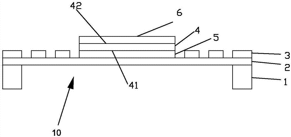
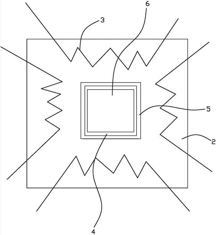
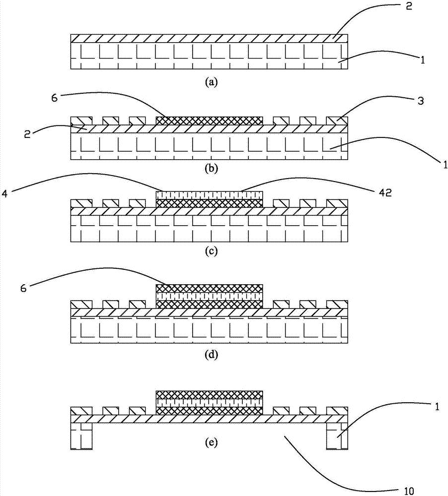
[0026] Such as figure 1 As shown, the piezoelectric ultrasonic transducer of this embodiment includes a substrate 1 , a diaphragm 2 fixed on the substrate 1 , and a piezoelectric film 4 attached to the diaphragm 2 . A cavity 10 is arranged at the center of the base 1 , and the diaphragm 2 is fixed on the base 1 and covers the cavity 10 .

[0027] The edge area of ​​the diaphragm close to the base 1 is provided with a resistive structure 3 that can generate Joule heat in an electrified state. The resistance structure 3 can increase the local temperature of the diaphragm 2, thereby changing the elastic coefficient of the diaphragm.

[0028] The piezoelectric film 4 includes a first surface 41 close to the diaphragm 2 and a second surface 42 away from the diaphragm 2 . The electrodes are electrode plates attached to the piezoelectric film 4 , specifical...


PUM


Abstract

The invention provides a piezoelectric ultrasonic transducer and a preparation method thereof. The piezoelectric ultrasonic transducer comprises a vibrating diaphragm and a piezoelectric diaphragm arranged on the vibrating diaphragm in an attached mode. A resistor structure capable of generating joule heat to enable the local temperature of the vibrating diaphragm to rise under the power-on state is arranged on a marginal area, close to a base, of the vibrating diaphragm. Because the vibrating diaphragm adopts materials of silicon dioxide and the like, wherein the Young modulus of the materials is reduced along with rising of the temperature, the integral elastic coefficient of the vibrating diaphragm can be reduced by heating, the electromechanical coupling factor of the transducer is increased, and sound pressure output is changed; and on the other hand, the resonant frequency when the vibrating diaphragm vibrates is reduced along with reducing of the elastic coefficient, and dynamic adjustment of an ultrasonic wave output frequency is achieved.

Description

technical field [0001] The invention relates to the field of ultrasonic sensors, in particular to a piezoelectric ultrasonic transducer and a preparation method thereof. Background technique [0002] Ultrasonic sensors have a wide range of applications in social production and life, including ultrasonic processing, ultrasonic positioning, ultrasonic detection, ultrasonic imaging and other aspects. As a device that converts electrical energy and mechanical energy, the ultrasonic transducer is an important component of the ultrasonic sensor. Traditional ultrasonic transducers are usually manufactured based on mechanical processing, so they have disadvantages such as large volume, low processing accuracy, high processing cost, and difficulty in forming an array structure. Ultrasonic transducers based on MEMS (Microelectromechanical Systems, microelectromechanical systems) technology are processed by microelectronics technology, the diameter size can be reduced to the micron le...

Claims


Application Information

Patent Timeline
Patent Type & Authority Applications(China)
IPC IPC(8): B06B1/06
CPCB06B1/0607
Inventor 朱雁青兰晓东童贝李杨
Owner AAC TECH PTE LTD
Why Eureka
Try Eureka