Bearing Ring Slant Oil Hole Processing Tooling

A technology of bearing rings and inclined oil holes, applied in the field of bearing processing, can solve problems such as difficult processing and difficult control, and achieve the effects of less processing difficulty, easy control, and reduced drilling depth

Active Publication Date: 2019-02-26
重庆市合川区云天机械制造有限公司
View PDF6 Cites 1 Cited by
  • Summary
  • Abstract
  • Description
  • Claims
  • Application Information

AI Technical Summary

Problems solved by technology

Since the operator only uses experience to make the corresponding positioning, it will inevitably cause the position deviation of the inclined oil hole, which is difficult to process and difficult to control

Method used


Image

  • Bearing Ring Slant Oil Hole Processing Tooling
  • Bearing Ring Slant Oil Hole Processing Tooling
  • Bearing Ring Slant Oil Hole Processing Tooling

Examples


Embodiment 1

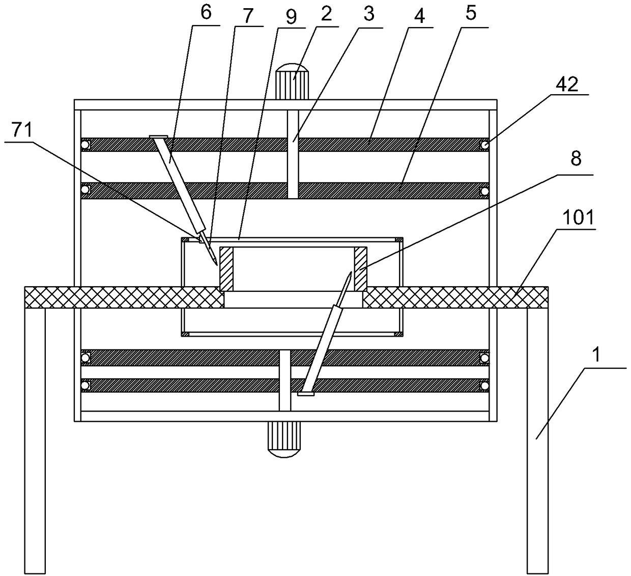
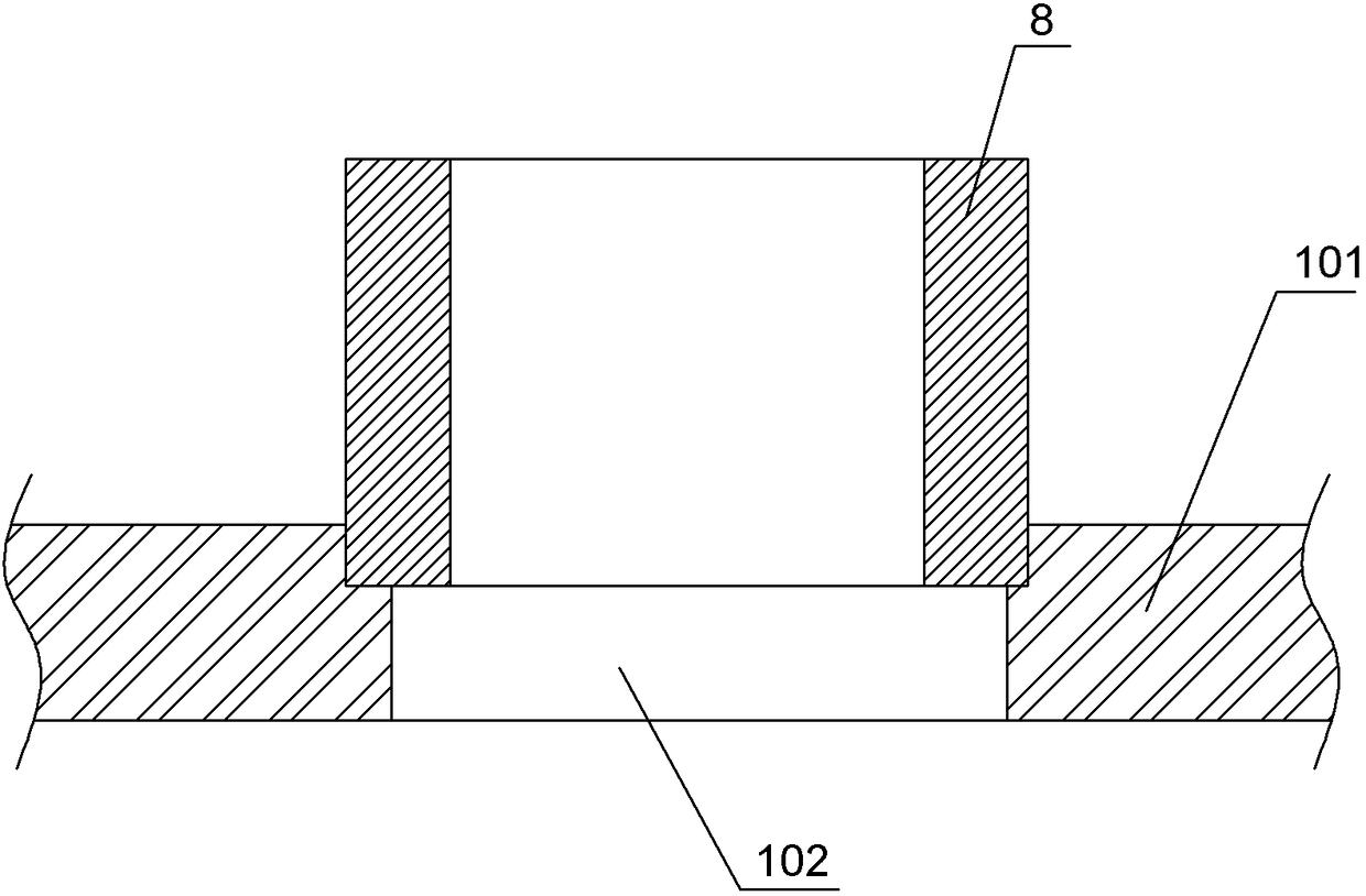
[0029] Embodiment 1 The bearing ring oblique oil hole processing device of the embodiment, such as figure 1 with figure 2 As shown, a frame 1 is included, and the table 101 of the frame 1 is an electromagnetic chuck. The table 101 is provided with a bearing ring fixing mechanism, and the bearing ring fixing mechanism includes a stepped hole 102 opened on the table 101 .

[0030] A rotating mechanism and a drilling mechanism are arranged above and below the table top 101 of the frame 1 .

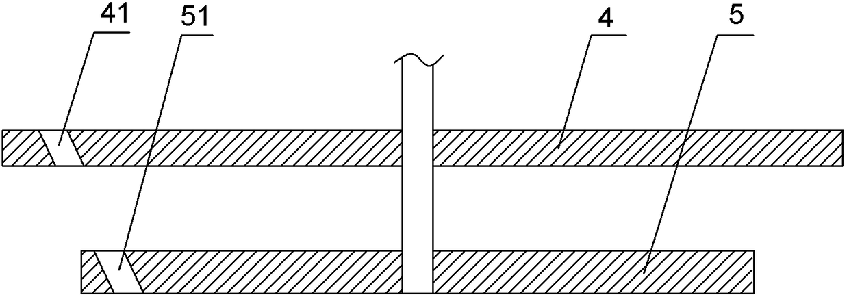
[0031] The rotating mechanism above includes a rotating shaft 3, a first turntable 4 and a second turntable 5. The rotating shaft 3 is connected to the frame 1 and is in a vertical state. A servo motor 2 is installed on the frame 1 above the rotating shaft 3. The servo motor 2 Used to drive the rotating shaft 3 to rotate, the centers of the first rotating disk 4 and the second rotating disk 5 are welded on the rotating shaft 3, the first rotating disk 4 and the second rotating disk 5 are in...

Embodiment 2

[0039] The difference between this embodiment and Embodiment 1 is:

[0040] The drilling depths of the two electric drills 7 are different. The drilling depth of the electric drill 7 above the table 101 of the frame 1 is 2 / 3 of the depth of the oblique oil hole of the bearing ring 8, and the electric drill 7 below the table 101 of the frame 1 The drilling depth is 1 / 3 of the oblique oil hole depth of the bearing ring 8, and the rotating shaft 3 turns a circle to complete the drilling of all oblique oil holes. When the electric drill 7 drilling is positioned at the top, the bearing ring 8 is not easy to shift, so the electric drill 7 drilling depth of the selection top is larger than the electric drill 7 drilling depth of the bottom.

Embodiment 3

[0042] The difference between this embodiment and Embodiment 1 is:

[0043] The drilling depths of the two electric drills 7 are different, and the times of drilling are different. The first drilling depth of the upper and lower electric drills 7 is 1 / 4 of the depth of the inclined oil hole, and the second drilling depth is the inclined oil hole. 1 / 2 of the depth. The rotating shaft 3 turns twice to complete the processing of all oblique oil holes. In this embodiment, compared with the first embodiment, the drilling depth of the same electric drill 7 is reduced, and the drill bit of the electric drill 7 is less likely to deviate or be broken.


PUM


Abstract

The invention belongs to the technical field of bearing machining, and discloses a bearing ring inclined oil hole machining tool. The bearing ring inclined oil hole machining tool comprises a rack, a step hole is formed in a table top of the rack, the table top of the rack is an electromagnetic chuck, and a rotating mechanism and a drilling mechanism are arranged above and below the table top of the rack; the rotating mechanism comprises a first rotary disc and a second rotary disc which are rotationally connected to the rack, rotating centers of the first rotary disc and the second rotary disc are coincident with a center shaft of the step hole, a first through hole is formed in the first rotary disc, a second through hole is formed in the second rotary disc, and the turning radius of the first through hole is larger than the turning radius of the second through hole; the drilling mechanism comprises a rotating rod and electric drills, the two electric drills are staggered in the circumferential direction of a bearing ring, and the sum of the drilling depths of the two electric drills is equal to the depth of a bearing ring inclined oil hole; and the rack is further provided with a rotating parking mechanism which comprises a plurality of microswitches and trigger blocks. When the bearing ring inclined oil hole machining tool is used for machining the bearing ring inclined oil hole, positioning is accurate, and the machining difficulty is small.

Description

technical field [0001] The invention relates to the technical field of bearing processing, in particular to a processing device for oblique oil holes of bearing rings. Background technique [0002] In order to prolong the service life of the bearing, an oblique oil hole for oil lubrication is usually provided on the bearing ring. In the process of machining the inclined oil hole of the existing bearing ring, the bearing ring is placed on a special drill tire for drilling the inclined oil hole, and the operator locates the position of the inclined oil hole with a square ruler and experience, and then completes the inclined oil hole processing operations. Because the operator only uses experience to make corresponding positioning, it will inevitably cause the position deviation of the inclined oil hole, which is difficult to process and difficult to control. Contents of the invention [0003] The object of the present invention is to provide a bearing ring inclined oil hol...

Claims


Application Information

Patent Timeline
Patent Type & Authority Patents(China)
IPC IPC(8): B23B41/00
CPCB23B41/00B23B2215/12
Inventor 张科
Owner 重庆市合川区云天机械制造有限公司
Why Eureka
Try Eureka