Barrel plating device and operation method thereof

A barrel plating and roller technology, applied in the direction of electrolysis process, electrolysis components, etc., can solve the problems of high cost, low efficiency, poor quality, etc., and achieve the effects of good stability, simple and fast operation, and simple structure

Inactive Publication Date: 2017-12-26
邓健康
View PDF0 Cites 4 Cited by
  • Summary
  • Abstract
  • Description
  • Claims
  • Application Information

AI Technical Summary

Problems solved by technology

[0003] The object of the present invention is to provide a barrel plating device and its operation method, which has a reasonable structure and aims to solve the technical deficiencies of low efficiency, poor quality and high cost of using the original electroplating method for larger parts in the traditional technology

Method used


Image

  • Barrel plating device and operation method thereof
  • Barrel plating device and operation method thereof
  • Barrel plating device and operation method thereof

Examples


Embodiment 1

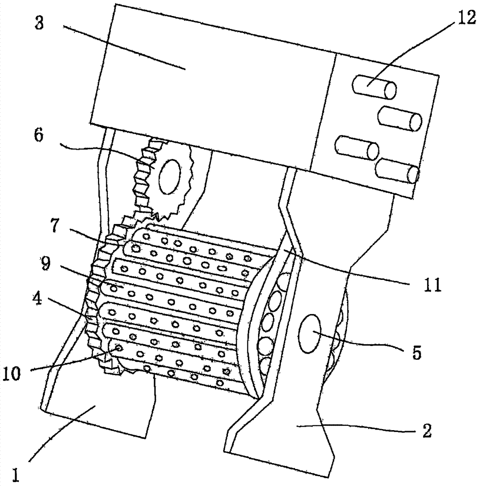
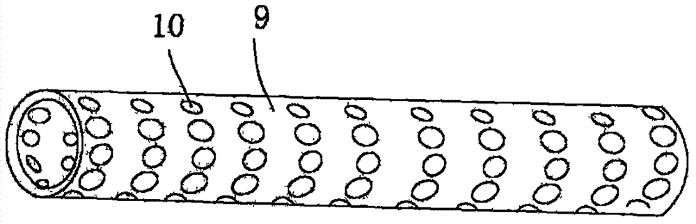
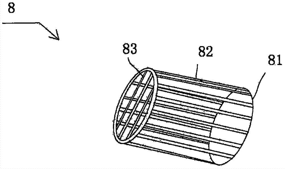
[0019] Figure 1 to Figure 3 A specific embodiment of the present invention is shown, wherein figure 1 Schematic diagram of the structure of the present invention; figure 2 Is a schematic diagram of the structure of the insulating tube of the present invention; image 3 Is a schematic diagram of the structure of the metal isolation cover of the present invention;

[0020] see Figure 1 to Figure 3 , A barrel plating device, the left support plate 1 and the right support plate 2, on the top of the left support plate 1 and the right support plate 2 is provided with a control box 3, on the left support plate 1 a roller sprocket 4 , The center of the roller gear plate 4 is connected to the middle of the left support plate 1 and the right support plate 2 through a rotating shaft 5. The roller gear plate is connected between the left support plate and the right support plate through the rotating shaft, which can facilitate the roller gear plate The rolling and connecting with the con...

Embodiment 2

[0031] Figure 4 A specific embodiment of the present invention is shown, wherein Figure 4 It is a flowchart of the operation method of the present invention.

[0032] A method for operating a barrel plating device includes the following steps:

[0033] Step A: Place the parts in the metal isolation cover. The parts in the metal isolation cover are always in reliable contact with the metal isolation cover under the action of gravity, and the metal isolation covers are pressed against each other through the plug or cover of the insulating tube to realize the metal isolation cover mutual At the same time, the metal isolation cover is reliably connected with the conductive ring in the drum gear plate, and the conductive ring is connected with the cathode wire of the power supply through the conductive metal shrapnel, so as to achieve reliable electrical conduction of all parts;

[0034] Step B: Start the drive motor, and drive the roller gear plate to rotate through the drive gear plat...


PUM


Abstract

The invention discloses a barrel plating device. A left support plate and a right support plate, a control box body, a drum toothed plate on the left support plate, a driving toothed plate on the left support plate, and evenly arranged on the drum toothed plate The circular hole is also provided with a metal isolation cover with one end inserted into the circular hole, an insulating tube is arranged on the outside of the metal isolation cover, and a driving motor and a rotating motor are arranged in the control box. A conductive ring is embedded in the toothed disc, the end of the metal isolation cover is inserted into the circular hole and pressed against the conductive ring, and a cathode conductive wire is arranged on the control box body. The invention has a simple structure, greatly improves the efficiency of electroplating, ensures the stability and uniformity of electroplating, and solves the technical deficiencies of low efficiency, poor quality and high cost in the traditional electroplating method for larger parts in the traditional technology. At the same time, the invention also discloses an operation method of the barrel plating device, which is simple and quick to operate, and can greatly improve the efficiency and quality stability of electroplating.

Description

Technical field [0001] The invention belongs to the technical field of electroplating equipment, and specifically relates to a barrel plating device and an operation method thereof. Background technique [0002] At present, there are three main methods for electroplating of bulk parts: barrel plating, vibration plating and rack plating. Vibration plating or rolling plating is not suitable for larger parts or parts that are easy to be wound or overlapped. The first two methods of plating for larger parts are prone to serious quality defects such as bumps and exposed bottom. Therefore, it is not used if the quality requirements are slightly higher. . Generally, rack plating is used. Even if rack plating is used, there are many defects: First, many parts need to be bound by copper wires or clamped by hanging tools during rack plating. This method has low production efficiency and requires a lot of labor. The quality of automatic line electroplating is not ideal, and there are ofte...

Claims


Application Information

Patent Timeline
Patent Type & Authority Applications(China)
IPC IPC(8): C25D17/20
CPCC25D17/20
Inventor 邓健康
Owner 邓健康
Why Eureka
Try Eureka