High-efficiency oil return device used for compressor oil-mist separator oil sump tank

A technology of oil mist separator and oil collection tank, which is applied in the direction of machines/engines, mechanical equipment, liquid variable capacity machinery, etc., can solve the problems of poor lubricating oil return, difficulty in cleaning, and oil accumulation in slow oil collection tanks, etc., to achieve Solve the effect of poor oil return, reasonable design and simple structure

Active Publication Date: 2017-12-26
CHINA PETROLEUM & CHEM CORP +1
View PDF7 Cites 0 Cited by
  • Summary
  • Abstract
  • Description
  • Claims
  • Application Information

AI Technical Summary

Problems solved by technology

In short, the function of the oil mist separator is to extract the oil mist in the oil tank and separate the oil mist from the air, so that the oil mist condenses into oil droplets and flows into the oil collection tank. When the oil collection tank is full, it will flow back through the overflow port. The oil pipe returns to the lubricating oil tank. However, the existing oil return device has the problem of poor lubricating oil return, resulting in the lubricating oil in the oil collecting tank not being able to return to the lubricating oil tank effectively or returning slowly so that the oil collecting tank accumulates more oil Difficult to clean up and creates a problem of lubricating oil waste

Method used


Image

  • High-efficiency oil return device used for compressor oil-mist separator oil sump tank

Examples


Embodiment

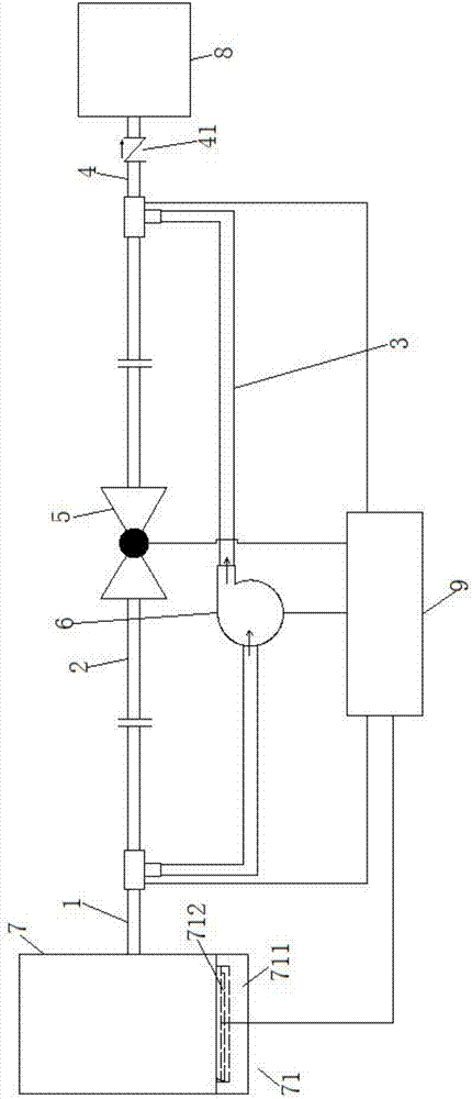
[0030] Example: such as figure 1 As shown, the high-efficiency oil return device applied to the oil collection tank of the compressor oil mist separator in this embodiment includes an oil outlet main pipe 1, a first branch pipe 2, a second branch pipe 3, an oil outlet secondary pipe 4, a ball valve 5 and an oil pump 6 ;

[0031] One end of the above-mentioned oil outlet main pipe 1 is connected with the oil outlet of the oil collection tank 7;

[0032] One end of the above-mentioned first branch pipe 2 and the second branch pipe 3 are respectively connected to the other end of the above-mentioned oil outlet main pipe 1, and the other ends of the above-mentioned first branch pipe 2 and second branch pipe 3 are respectively connected to one end of the above-mentioned oil outlet auxiliary pipe 4;

[0033] The other end of the oil outlet secondary pipe 4 is connected to the oil return port of the lubricating oil tank 8;

[0034] The above-mentioned ball valve 5 is connected and ...


PUM


Abstract

The invention relates to lubricating oil return devices, in particular to a high-efficiency oil return device used for a compressor oil-mist separator oil sump tank. The high-efficiency oil return device used for the compressor oil-mist separator oil sump tank comprises an oil outlet main pipe, a first branch pipe, a second branch pipe, an oil outlet assistant pipe, a ball valve and an oil pump. One end of the oil outlet main pipe is connected with an oil outlet of the oil sump tank. One end of the first branch pipe and one end of the second branch pipe are connected with the other end of the oil outlet main pipe. The other end of the first branch pipe and the other end of the second branch pipe are connected with one end of the oil outlet assistant pipe. The other end of the oil outlet assistant pipe is connected with an oil return port of a lubricating oil tank. The ball valve is mounted on the first branch pipe and communicates with the first branch pipe. The oil pump is mounted on the second branch pipe and communicates with the second branch pipe. The high-efficiency oil return device has the advantages that the structure is simple, design is reasonable, and the problem that oil does not return smoothly from the oil sump tank to the lubricating oil tank.

Description

technical field [0001] The invention relates to a lubricating oil return device, in particular to a high-efficiency oil return device applied to an oil collection tank of an oil mist separator of a compressor. Background technique [0002] When lubricating oil lubricates and cools the high-speed rotating bearing bush of the compressor and motor, the lubricating oil is violently collided and evaporated at high temperature, and the dry gas seal isolates the gas to purge the moving lubricating oil to generate a large amount of oil mist. The oil mist enters from the inlet of the oil mist separator and passes through the aluminum-coated glass fiber antistatic filter cartridge to condense most of the oil mist into oil droplets and flow into the lower oil collection tank, and the rest of the oil mist passes through the fine filter barrel to condense most of the oil mist into oil droplets Collecting the oil tank, only a small part of the oil mist is discharged into the atmosphere th...

Claims


Application Information

Patent Timeline
Patent Type & Authority Applications(China)
IPC IPC(8): F04B39/02F04B39/06
CPCF04B39/0207F04B39/0284F04B39/06
Inventor 王俭王会坤王子龙杨松曾强宗子轩黄巍尹晨晖边明
Owner CHINA PETROLEUM & CHEM CORP
Why Eureka
Try Eureka