
Target boundary extraction method based on laser stripe geometric feature mutation

A geometric feature and boundary extraction technology, applied in the field of visual measurement, which can solve problems such as misalignment, different levels and widths of light bar grayscale distribution, disconnection and discontinuity, etc.

Active Publication Date: 2017-12-26
DALIAN UNIV OF TECH
View PDF9 Cites 10 Cited by
  • Summary
  • Abstract
  • Description
  • Claims
  • Application Information

AI Technical Summary

Problems solved by technology

[0006] In order to solve the limitations in the process of measuring the boundary profile information of large aeronautical components in the assembly process under the existing large field of view, the present invention invented a boundary extraction method based on the sudden change of the geometric characteristics of the laser light strip
It overcomes the many noise points at both ends of the light strip during the existing boundary extraction process; due to the influence of the spatial position relationship, the laser light strip presents bending, dislocation or disconnection and discontinuity; the gray level of the light strip presents And the width is not the same problem, has a wide range of application prospects

Method used


Image

  • Target boundary extraction method based on laser stripe geometric feature mutation
  • Target boundary extraction method based on laser stripe geometric feature mutation
  • Target boundary extraction method based on laser stripe geometric feature mutation

Examples


Embodiment Construction

[0051] The specific embodiments of the present invention will be described in detail below in conjunction with technical methods and accompanying drawings.

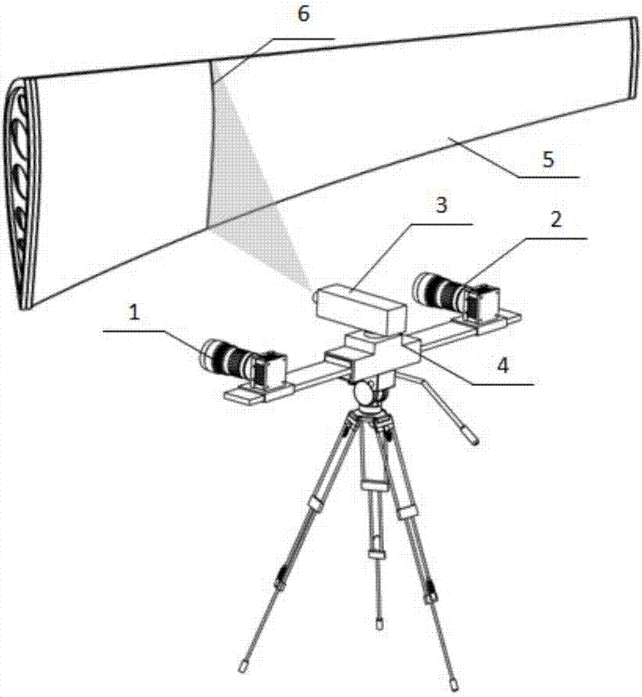
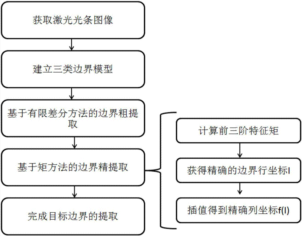
[0052] First, by combining laser with binocular vision, the left and right cameras 1 and 2 are used to shoot the auxiliary laser stripes 6 formed by the laser emitter 3 on the measured object 5 to obtain the image of the laser stripes 6; secondly, according to the main In the case of existing boundary light strips, establish three types of boundary models; then, use the differential operation to derive the boundary feature vector h to obtain the coordinates of the roughly extracted target boundary feature points; finally, according to the principle of moment invariance, obtain the finely extracted target boundary Feature point coordinates; the specific steps of the method are as follows:

[0053] The first step is to obtain point cloud data

[0054] This measurement selects the VC‐12MC‐M / C 65 industrial camera produced b...


PUM


Abstract

The invention belongs to a target boundary extraction method based on laser stripe geometric feature mutation, which belongs to the field of visual measurement. The method comprises steps: a mode of combining laser and binocular vision is firstly adopted to acquire a laser stripe image; according to a boundary laser stripe condition existing in an actual measurement process, three kinds of boundary models are built; differentiate operation is used to carry out derivation on a boundary eigenvector, and target boundary feature point coordinates through rough extraction are obtained; and according to a moment invariance principle, target boundary feature point coordinates through fine extraction are obtained, and quick and high-precision extraction on the target boundary is realized. The method overcomes phenomena that during the existing boundary extraction process, many noisy points are generated at the boundary of two ends of the laser stripe, and due to influences of a spatial position relationship, the laser stripe is bent, dislocated or broken and disconnected and the gray distribution level and the width presented by the laser stripe are different, and quick and high-precision target boundary extraction is realized.

Description

technical field [0001] The invention belongs to the field of visual measurement, and relates to a target boundary extraction method based on sudden changes in the geometric characteristics of light bars. Background technique [0002] For the three-dimensional measurement of large aerospace components (such as aircraft flat and vertical tail parts, etc.) in accordance with. In the data acquisition process of the laser measurement system, theoretically, the line laser beam has a Gaussian distribution along the cross-sectional direction, and the light intensity distribution along the light strip direction is uniform and has a consistent width within a certain range. However, in the actual measurement process, there are mainly five boundary light stripe conditions: light stripe bending, light stripe misalignment, light stripe disconnection, light stripe gray scale mutation, and light stripe width mutation. [0003] Due to the complex environment of the measurement site, the ma...

Claims


Application Information

Patent Timeline
Patent Type & Authority Applications(China)
IPC IPC(8): G06T7/521G06T7/00G01C11/04
CPCG01C11/04G06T7/0004G06T7/521G06T2207/30164
Inventor 刘巍赵海洋叶帆张致远兰志广张洋马建伟贾振元
Owner DALIAN UNIV OF TECH
Learn More