Three-dimensional foot laser scanner
A laser scanner and foot technology, applied in the field of foot scanners, can solve the problems of time-consuming measurement accuracy, low integration and flexibility, low work efficiency, etc. High efficiency and improve work efficiency
- Summary
- Abstract
- Description
- Claims
- Application Information
AI Technical Summary
Problems solved by technology
Method used
Image
Examples
Embodiment 1
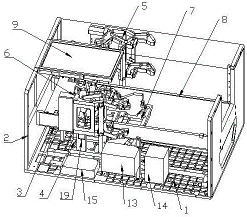
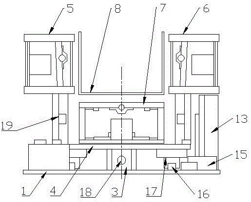
[0025] Example 1, such as Figure 1-2As shown, a three-dimensional foot laser scanner includes an electromechanical system, an optical system and a data processing system connected to each other; the optical system of the present invention uses laser light in three directions to irradiate the surface of the measured object, and simultaneously uses three corresponding A camera is used to acquire images, and the corresponding mechanical design is carried out according to the optical path diagram we designed, so that each camera can obtain two images that do not interfere with each other, and then use the computer program of the data processing system to process, and adopt the bionic human eye stereoscopic vision technology. Form a three-dimensional three-dimensional model with the front intersection method and the rear intersection method to obtain the three-dimensional space data of the measured object, and then make an accurate and suitable shoe last. Among them, the electrome...
Embodiment 2
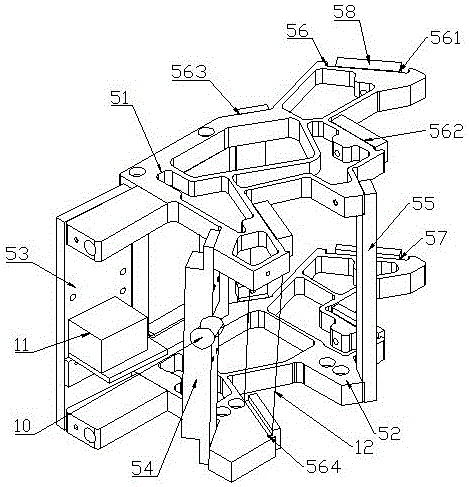
[0028] Example 2, such as image 3 and 6 As shown, a three-dimensional foot laser scanner, the left optical machine module 5 and the right optical machine module 6 both include an upper support plate 51 and a lower support plate 52, and the upper support plate 51 and the lower support plate 52 pass through the The camera bracket 53 , the laser bracket 54 are connected with the connecting plate 55 , the CCD camera 11 is installed on the camera bracket 53 , and the laser 10 is installed on the laser bracket 54 . The upper support plate 51 is provided with four upper fixed platforms 56, and the lower support plate 52 is provided with four lower fixed platforms 57, and the upper fixed platform 56 corresponds to the lower fixed platform 57; the upper fixed platform 56 is connected to the lower fixed platform. On the platform 57, the first fixed block 58 for fixing the reflector 12 is movable, the upper end of the reflector 12 is connected with the upper fixed platform 56 by the fi...
Embodiment 3
[0032] Example 3, such as Figure 4 , 5 As shown in , 7, a three-dimensional foot laser scanner, the lower optical machine module 7 includes a left support plate 71 and a right support plate 72, and the left support plate 71 and the right support plate 72 pass through the lower base plate 73 and the upper base plate respectively 74 are connected, a CCD camera 11 is installed on the lower base plate 73, and a laser 10 is installed on the upper base plate 74. Described left support plate 71 is provided with five left fixed platforms 75, and right support plate 72 is provided with five right fixed platforms 76, and left fixed platform 75 corresponds to right fixed platform 76 one by one, and left fixed platform 75 and right fixed platform The second fixed block 77 that is used to fix the reflector 12 is all movable on the platform 76, and the left end of the reflector 12 is connected with the left fixed platform 75 by the second fixed block 77, and the right end of the reflector...
PUM
 Abstract
Description
Claims
Application Information
 - R&D
- Intellectual Property
- Life Sciences
- Materials
- Tech Scout
- Unparalleled Data Quality
- Higher Quality Content
- 60% Fewer Hallucinations
Browse by: Latest US Patents, China's latest patents, Technical Efficacy Thesaurus, Application Domain, Technology Topic, Popular Technical Reports.
© 2025 PatSnap. All rights reserved.Legal|Privacy policy|Modern Slavery Act Transparency Statement|Sitemap|About US| Contact US: help@patsnap.com


