[0022] The specific embodiments of the present invention will be described in detail below with reference to the accompanying drawings.
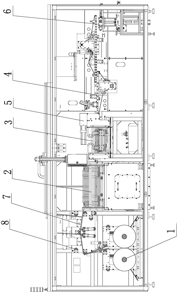
[0023] Such as figure 1 As shown, the lithium battery pole piece double strip high-speed die-cutting machine of the present invention includes a material tray unwinding mechanism 1, a plurality of guide rollers 8, a correction mechanism, a servo press for forming pole piece tabs, and a tape traction mechanism 3. The cutter assembly 5 for cutting the material tape, and the material conveying system 4, the material tray unwinding mechanism 1 includes two independent unwinding shafts 1.1, and each unwinding shaft 1.1 corresponds to a correction mechanism and a material belt traction The mechanism 3 and a cutter assembly 5 are provided with two sets of punch assemblies on the servo press, and each set of punch assemblies corresponds to a strip.
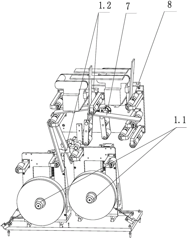
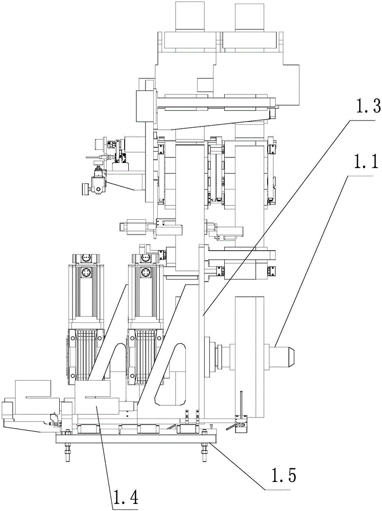
[0024] Such as figure 2 with image 3 As shown, each correction mechanism includes two correction sensors 1.2 and one correction device. The correction sensors 1.2 are located at different positions in the forward direction of the material belt. The correction sensors on the two correction mechanisms are arranged parallel to each other. The correction device is connected to the unwinding shaft to drive it to move in the axial direction. The correction device includes a vertical fixing plate 1.3, a bottom plate 1.5, and a deviation correction motor 1.4. The deviation correction motor 1.4 is arranged on the bottom plate 1.5. The bottom plate 1.5 is provided with a slide rail. The fixed plate 1.3 is provided with a slide that matches the slide rail. Block, the unwinding shaft 1.1 is arranged on the fixed plate, the slide rail is arranged parallel to the unwinding shaft, the correction motor 1.4 drives the fixed plate to slide along the slide rail, thereby driving the unwinding shaft 1.1 to move in the axial direction.
[0025] When each material belt is equipped with a correction sensor, when the correction sensor detects the deviation of the material belt, the correction device actuates the movement of the unwinding shaft, which may cause the material belt to tilt, resulting in the two material belts not being parallel and the material belt is not parallel. Parallelism causes synchronization problems, and the stamping position of the servo press on the two strips may also be offset. However, two correction sensors are used, and the line of the correction sensors corresponding to the two material belts is arranged in parallel, which can prevent the axial movement of the unwinding shaft and cause the material belt to tilt and ensure the parallelism of the two material belts.
[0026] Such as Figure 4 As shown, the lithium battery material belt high-speed servo press of the present invention includes an upper template 2.4, a lower template 2.3, a mounting plate 2.5, a base 2.2, a base plate 2.7, a number of guide posts 2.6, and a driving mechanism for forming the material. The main mechanism includes a driving motor and a cam mechanism. The driving motor drives the cam mechanism to rotate. The rotation of the cam drives the upper template to move up and down along the guide column. The upper template 2.4 is fixed on the mounting plate 2.5, and the mounting plate 2.5 is fixed with the guide column 2.6. The column passes through the base 2.2, a base plate 2.7 is provided on the base 2.2, and the lower template 2.3 is provided on the base plate 2.7. The base plate 2.7 is provided with two lifting mechanisms. The upper surface of the lifting mechanism can protrude from the base plate 2.7. And push out the lower mold plate to separate it from the upper surface of the substrate 2.7.
[0027] The mass of the mounting plate 2.5 is between 90 and 110 kg, and it is an integral structure with the upper template. The upper surface of the mounting plate is provided with a plurality of reinforcing ribs for keeping the mounting plate stable and preventing deformation. The integral molding and rib design can prevent the deformation and loosening of the upper template and the mounting plate during the high-speed stamping process, and maintain the high precision of stamping.
[0028] Such as Figure 5 As shown, the lifting mechanism refers to: two limit slots 2.13 are provided on the base plate 2.7, each limit slot 2.13 is provided with a horizontal slide bar 2.11 and a longitudinal slide bar 2.9, and a limit slot 2.13 is provided with The vertical limit screw 2.10 is fixed on the base plate 2.7. The limit screw 2.10 is composed of an upper section and a lower section. The horizontal slide bar 2.11 is provided with a chute. The lower section of the limit screw 2.10 can slide horizontally in the chute. The upper section of the limit screw 2.10 is tightly fitted with the longitudinal sliding strip 2.9 to limit its horizontal sliding. The upper surface of the horizontal sliding strip 2.11 is provided with at least two slope-shaped protrusions 2.12, and the side profile of the protrusions 2.12 is trapezoidal, The lower surface of the longitudinal slide bar 2.9 is provided with a groove that cooperates with the protrusion 2.12. The longitudinal slide bar 2.9 is provided above the horizontal slide bar, and the two are movably matched through the protrusion and the groove. The part is provided with a rotating mechanism for lateral movement of the slide bar.
[0029] When the template needs to be installed and removed, the horizontal slide bar is slid through the rotating mechanism, so that the protrusion draws the groove of the longitudinal slide bar. Due to the function of the stop screw, the longitudinal slide bar will not be positioned horizontally, so that the vertical slide bar Lifting, thereby reducing the direct contact between the upper template and the substrate, reducing the wear of the lower template, thereby improving the slicing accuracy. The lifting mechanism also includes a flexible protective strip 2.8, which is fixed above the longitudinal sliding strip.
[0030] The rotating mechanism includes a connecting block 2.15, a fixed block 2.17, an eccentric column 2.16, and a wrench 2.18. The fixed block 2.17 is fixed on the side of the base plate. The eccentric column 2.16 is rotatably arranged on the fixed block 2.17. The two ends of the connecting block 2.15 are respectively It is rotatably connected with one end of the horizontal sliding bar and the eccentric column 2.16, and a wrench 2.18 is arranged at both ends of the eccentric column for rotating the eccentric column.
[0031] The servo press is mainly used for forming the tabs of the lithium battery pole pieces. The material belt enters the belt traction mechanism 3 after passing through the servo press. Each belt traction mechanism 3 mainly includes a set of clamping jaws, which can move back and forth and up and down. , The gripper clamps the material belt to drive the material belt forward.
[0032] Two sets of cutter assemblies 5 are arranged above the discharge of the material belt traction mechanism 3, which are precisely driven by a servo cam. The cutter assembly 5 cuts the material tape into a single pole piece, and the material conveying system 4 is arranged at the outlet of the material belt traction mechanism 3 to transport the material pieces.
[0033] The material conveying system 4 includes two material transplanting mechanisms and two dust removal mechanisms; each material transplanting mechanism includes a material track and two conveyor belts arranged on the track, and each conveyor belt corresponds to a pole on a material belt. Negative pressure air holes are provided on the sheet, the material track and the conveyor belt. The transmission belt adopts a perforated tape. The negative pressure air holes are connected to the negative pressure joint, and the negative pressure joint is connected to the negative pressure air source, so that the surface of the conveyor belt has a negative pressure adsorption tray , The conveyor belt moves on the material track under the action of the servo motor.
[0034] The conveyor belt of the material transplanting mechanism close to the cutter assembly faces upwards, the reverse side of the adsorbing material causes the material to move on the upper surface of the conveyor belt, and a dust removal mechanism is arranged above the material transplanting mechanism for dust removal on the front of the material. The conveyor belt of the other material transplanting mechanism faces downwards, the front side of the adsorbing material makes the material move on the lower surface of the conveyor belt, and another dust removal mechanism is arranged under the material transplanting mechanism for dust removal on the reverse side of the material; two The material tracks of the material transplanting mechanism cooperate with each other. The dust removal mechanism can be a powerful air blowing device or an electrostatic dust removal device, both of which are not described here. By setting two material transplanting mechanisms to adsorb the front and back sides of the material respectively, the two sides of the material can be completely cleaned, thereby ensuring the quality of the material.
[0035] Two pole piece sizing devices 6 are provided below the end of the belt conveyor 4, corresponding to a conveyor belt, such as Image 6 As shown, the device includes a base 6.10, a first baffle 6.9, a second baffle 6.4, a third baffle 6.3, and a pushing mechanism. The first baffle 6.9, the second baffle 6.4, and the third baffle 6.3 are enclosed by In the space where the pole piece is placed, the first baffle, the second baffle, the third baffle and the top inner side of the limit bar are all provided with inclined surfaces for guiding materials. The first baffle 6.9 and the second baffle 6.4 are fixedly arranged on the base 6.10 and are perpendicular to each other. The third baffle 6.3 and the second baffle 6.4 are perpendicular to each other. The third baffle 6.3 is connected to a pushing mechanism, which drives the third The translation of the baffle 6.3 pushes one of the sides of the pole piece to fit the first baffle.
[0036] A pushing mechanism is also provided on the opposite side of the second baffle. The two ends of the pushing mechanism are provided with a limit bar 6.8 respectively. The limit bar 6.8 is translated in the function of the pushing mechanism, and the limit bar 6.8 pushes the pole piece with tabs. The pole piece is attached to the inner side of the second baffle 6.4.
[0037] The pushing mechanism includes a fixed base plate 6.2, a movable plate 6.1, a rotating shaft 6.6, and an eccentric wheel 6.7. The fixed base plate 6.2 can be fixed on the base 6.10. The position of the rotating shaft 6.6 is fixedly arranged relative to the fixed base plate 6.2, so the rotating shaft 6.6 can be fixed on the base 6.10 It is also possible to set the rotating shaft on the fixed base plate 6.2, the eccentric wheel 6.7 is eccentrically arranged on the rotating shaft 6.6, the rotating shaft 6.6 is arranged parallel to the movable plate 6.1, the two ends of the movable plate 6.1 are provided with guide posts 6.11, and the guide posts 6.11 pass through the fixed The base plate 6.2, the third baffle plate 6.3 and the limit bar 6.8 are all installed at the end of the guide post 6.11, and the outer peripheral surface of the eccentric wheel directly or indirectly contacts the movable plate, driving the movable plate 6.11 to move.
[0038] The rotating shaft is driven by the motor to rotate to drive the rotation of the eccentric wheel. The displacement driven by the eccentric wheel drives the displacement of the movable plate, thereby driving the back and forth movement of the guide post, thereby driving the movement of the limit bar and the third baffle, and then the stacked material Carry out the monolith.
[0039] The fixed base plate is provided with a hollow part corresponding to the eccentric wheel for rotation of the eccentric wheel, and a number of driven wheels 6.5 are also provided on the movable plate 6.1. The axis of the driven wheel 6.5 is arranged in parallel with the eccentric wheel 6.6, and the driven wheel and the eccentric wheel are movably matched. Setting the driven wheel can reduce the direct friction between the eccentric wheel and the movable plate and prolong the service life.