Thin film forming apparatus

A technology of thin film and raw material gas, applied in gaseous chemical plating, metal material coating process, coating, etc., can solve the problems of unbalanced pressure and low reactivity in the gas stagnation chamber 40, and achieve improved reactivity, The effect of saving raw materials and reducing the generation of growth-type foreign matter

Active Publication Date: 2017-12-29
HB TECH CO LTD
View PDF6 Cites 3 Cited by
  • Summary
  • Abstract
  • Description
  • Claims
  • Application Information

AI Technical Summary

Problems solved by technology

[0003] On the same parallel line 2 as the supply direction of the raw material gas supplied to the gas retention chamber 40 , the first exhaust part 50 , the first gas discharge part 60 and the second exhaust part are formed to the rear of the supply direction of the raw material gas. Two e

Method used


Image

  • Thin film forming apparatus
  • Thin film forming apparatus
  • Thin film forming apparatus

Examples


Embodiment Construction

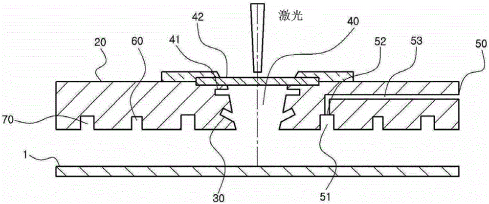
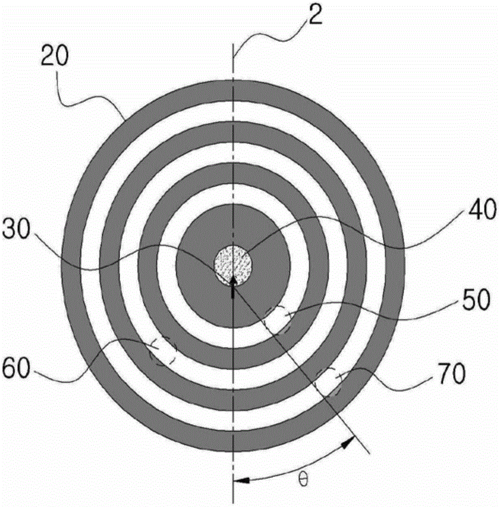
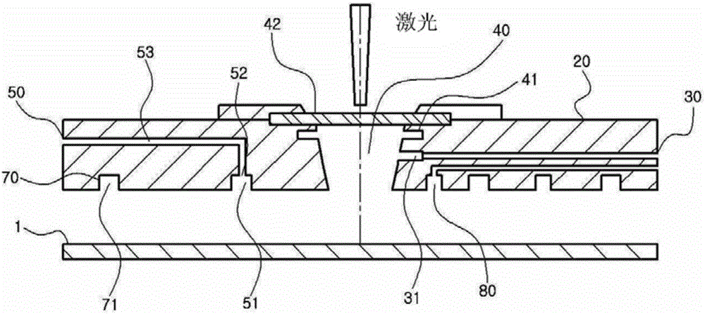
[0032] Hereinafter, preferred embodiments of the present invention will be described with reference to the drawings. In this process, the thickness of a plurality of lines or the size of structural elements shown in the drawings may be exaggerated for the sake of clarity and convenience of description.

[0033] In addition, a plurality of terms described later are terms defined in consideration of functions in the present invention, and may differ according to the user's or operator's intention or custom. Therefore, the definitions of such multiple terms should be performed according to the entire contents of this specification.

[0034] Moreover, the following examples do not limit the scope of claims of the present invention, but are merely illustrative matters of the structural elements proposed in the scope of claims of the present invention, include the technical ideas in the full text of the description of the present invention and include Among the structural elements ...


PUM


Abstract

According to an aspect of the present invention, there is provided a method of manufacturing a semiconductor device, including: supplying a CVD (Chemical Vapor Deposition) raw material gas onto a surface of a substrate, irradiating the supplied raw material gas with laser light, A thin film forming apparatus for forming a thin film on a substrate, comprising: a chamber unit provided on the substrate; a chamber supply unit for supplying a source gas to the chamber unit; a gas supplying unit and a second exhaust unit for exhausting a gas and a raw material gas, wherein a gas flow in the gas retention chamber is formed in a gas retention chamber, a first exhaust unit for exhausting a raw material gas discharged from the gas retention chamber, forming means for forming a uniform pressure in all directions of the gas retention chamber is formed in order to make the gas retention chamber uniform It is a ball.

Description

technical field [0001] The present invention relates to a thin film forming apparatus, and more particularly, to a thin film forming apparatus for correcting defects of substrates having a planar pattern structure such as photomasks and liquid crystal substrates. Background technique [0002] figure 1 is a cross-sectional view of a conventional thin film forming apparatus, figure 2 It is a top view of a conventional thin film forming apparatus, refer to Figure 1 to Figure 2 , in the conventional thin film forming apparatus, a chamber unit 20 is provided on the upper part of the substrate 1, and the chamber unit 20 includes: a raw material supply mechanism 30 for supplying raw material gas; a gas retention chamber 40 for making the above-mentioned The raw material gas supplied by the raw material supply mechanism 30 is retained; the first exhaust part 50 is used to discharge the raw material gas discharged from the gas retention chamber 40; the first gas discharge part 60...

Claims


Application Information

Patent Timeline
IPC IPC(8): C23C16/455C23C16/48
CPCC23C16/45563C23C16/48C23C16/4401C23C16/4412C23C16/45502C23C16/483
Inventor 郭东周申东镐
Owner HB TECH CO LTD
Why Eureka
Try Eureka