Dense optical flow estimation method and device

A dense optical flow and estimation algorithm technology, applied in the field of computer vision, can solve problems such as poor accuracy, long time-consuming search and query operations, difficulty in obtaining dense optical flow, etc., and achieve fast results

Active Publication Date: 2017-12-29
BEIJING TUSEN ZHITU TECH CO LTD
View PDF6 Cites 17 Cited by
  • Summary
  • Abstract
  • Description
  • Claims
  • Application Information

AI Technical Summary

Problems solved by technology

However, the block matching algorithm is a local non-parametric method, which ignores the global context information of the image, resulting in the initial value of the optical flow of many points being the local optimum value, although the subsequent filtering operation filters out some points with the local optimum value, However, the bad initial value of the optical flow of the unfiltered points will still cause great damage to the final dense optical flow, and a large number of search q

Method used


Image

  • Dense optical flow estimation method and device
  • Dense optical flow estimation method and device
  • Dense optical flow estimation method and device

Examples


Embodiment 1

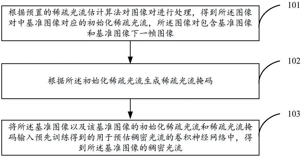
[0025] see figure 1 , is a flow chart of the dense optical flow estimation method in the embodiment of the present invention, the method includes:

[0026] Step 101. Process the image pair according to the preset sparse optical flow estimation algorithm to obtain the initialized sparse optical flow corresponding to the reference image in the image pair. The image pair includes the reference image and the next frame image of the reference image.

[0027] Preferably, in the embodiment of the present invention, the sparse optical flow estimation algorithm may be the Lucas-Kanade algorithm, and the initialization of the sparse optical flow obtained by processing the image degree through the Lucas-Kanade algorithm is accurate and fast.

[0028] In the embodiment of the present invention, the image pair refers to the image pair formed by the image to be estimated dense optical flow and the next frame image of the image. The image to be estimated dense optical flow is called the ref...

Embodiment 2

[0049] Based on the same idea as the dense optical flow estimation method provided in the first embodiment, the second embodiment of the present invention also provides a dense optical flow estimation device, the structure of which is as follows Figure 4 shown, including:

[0050] The processing unit 41 is configured to process the image pair according to the preset sparse optical flow estimation algorithm to obtain the initialized sparse optical flow corresponding to the reference image in the image pair, the image pair including the reference image and the next frame image of the reference image .

[0051] Preferably, the sparse optical flow estimation algorithm is Lucas-Kanade algorithm.

[0052] A generating unit 42, configured to generate a sparse optical flow mask according to the initialized sparse optical flow.

[0053] The generation unit 42 is specifically configured to: mark the pixels containing sparse optical flow in the reference image as 1, and mark the pixel...


PUM


Abstract

The invention discloses a dense optical flow estimation method and device to improve the accuracy and efficiency of dense optical flow estimation. The method includes the following steps: processing an image pair according to a preset sparse optical flow estimation algorithm to get an initial sparse optical flow corresponding to a reference image in the image pair, wherein the image pair includes a reference image and a frame of image next to the reference image; generating a sparse optical flow mask according to the initial sparse optical flow; and inputting the reference image and the initial sparse optical flow and the sparse optical flow mask of the reference image to a pre-trained convolutional neural network for optical flow mask estimation to get a dense optical flow of the reference image.

Description

technical field [0001] The invention relates to the field of computer vision, in particular to a dense optical flow estimation method and device. Background technique [0002] In the field of computer vision, Optical Flow describes the trajectory of pixels in an image or the correspondence between a pair of pixels in an image. Optical flow generally includes sparse optical flow (Sparse Flow) and dense optical flow (DenseFlow). Sparse optical flow generally describes salient feature points (such as corner points), while dense optical flow describes all pixels of an image. In image processing tasks such as behavior recognition and motion prediction, optical flow plays a very important role as a motion feature. Therefore, how to accurately estimate optical flow (especially dense optical flow) in the field of computer vision is particularly important. [0003] The traditional dense optical flow estimation method generally includes the following four steps: step 1, optical flo...

Claims


Application Information

Patent Timeline
IPC IPC(8): G06T7/269G06N3/04
CPCG06T7/269G06T2207/20084G06T2207/20081G06N3/045
Inventor 卢远勤王乃岩
Owner BEIJING TUSEN ZHITU TECH CO LTD
Why Eureka
Try Eureka