Link Error Detection and Diagnosis Method and Device Based on Digital Optical Fiber Distribution System

A digital optical fiber distribution and bit error detection technology, which is applied in transmission systems, electromagnetic wave transmission systems, electrical components, etc., can solve problems such as inability to access the coverage network, aging of optical modules, and bit errors, so as to reduce manual troubleshooting costs, The effect of reducing the influence of bit errors and improving communication efficiency

Active Publication Date: 2019-12-10
WUHAN HONGXIN TELECOMM TECH CO LTD
View PDF10 Cites 0 Cited by
  • Summary
  • Abstract
  • Description
  • Claims
  • Application Information

AI Technical Summary

Problems solved by technology

[0003] However, in actual engineering applications, due to fiber fusion technology, abnormal optical fiber aging, abnormal optical module interface, optical module aging and other abnormal problems, it will cause bit errors in the optical transmission process, which will affect the use of business functions and data transmission. What is particularly serious is that if a large number of bit errors occur in the uplink of one of the remote radio frequency units, then a large amount of uplink error data is transmitted to the only access unit of the system through cascade summation, which will directly affect the entire system The coverage quality of the network may even cause the entire coverage network to be completely inaccessible in severe cases. Therefore, it is possible to provide a method for quickly locating nodes that generate bit errors, quickly dealing with problem nodes, and proactively reporting the information of problem nodes. especially meaningful

Method used


Image

  • Link Error Detection and Diagnosis Method and Device Based on Digital Optical Fiber Distribution System
  • Link Error Detection and Diagnosis Method and Device Based on Digital Optical Fiber Distribution System
  • Link Error Detection and Diagnosis Method and Device Based on Digital Optical Fiber Distribution System

Examples


Embodiment Construction

[0027] The present invention will be further described in detail below in conjunction with the embodiments and the accompanying drawings, but the embodiments of the present invention are not limited thereto.

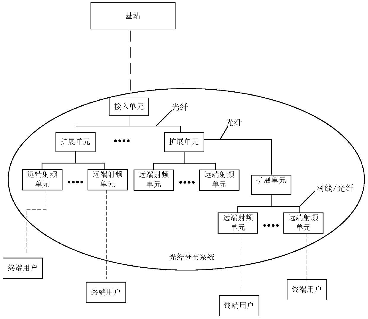
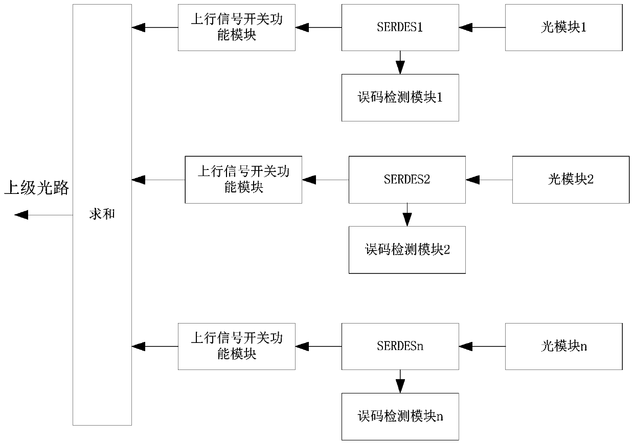
[0028] The present invention proposes a link error detection and diagnosis method based on a digital optical fiber distribution system, adding an error detection module and an uplink signal switch function module at the service transmission physical interface of each node,

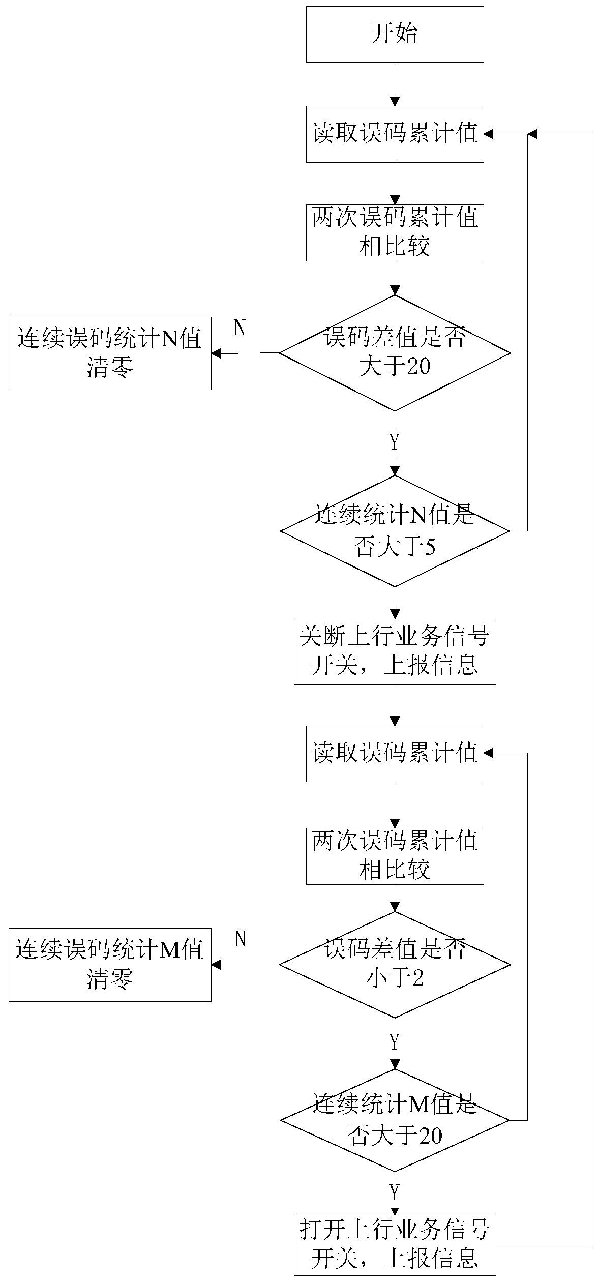
[0029] When a bit error occurs at any service transmission physical interface in the digital optical fiber distribution system, the cumulative number of bit errors detected by the bit error detection module at the corresponding node is used to calculate the difference in the cumulative number of bit errors in adjacent unit time periods, Obtain the change of bit error; based on the change of bit error, through the diagnosis mechanism, the uplink service data signal is managed through the uplink signal ...


PUM


Abstract

The invention provides a link error code detection and diagnostic method and a link error code detection and diagnostic device based on a digital optical fiber distribution system. An error code detection module and an uplink signal switch function module are added at a service transmission physical interface of each node, when error codes are generated at any service transmission physical interface in the digital optical fiber distribution system, the accumulated number of the error codes detected by the error code detection module at the corresponding node, a difference between the accumulated error code numbers in adjacent unit time slots is computed to acquire a variation condition of the error codes; a fast-close slow-open mode is used for managing an uplink service data signal via an uplink signal switch function module at the corresponding node via a diagnostic mechanism based on the variation condition of the error codes, and thus influence of the error codes is reduced. According to the method and the device provided by the invention, the phenomenon of whole system exception can be avoided, and meanwhile information of the node where the error codes are generated is recorded and uploaded to a monitoring center, so as to be convenient for engineers to troubleshoot.

Description

technical field [0001] The invention relates to a digital optical fiber distribution communication system, in particular a method for detecting and diagnosing link error codes based on the digital optical fiber distribution system. Background technique [0002] The multi-standard digital optical fiber distribution system is mainly characterized by the use of optical fiber resources as the transmission medium to improve signal coverage. It has extremely high application value in the outdoors of dense buildings, the construction of indoor distribution systems in new buildings, and FTTH communities with existing optical fiber resources; The system consists of three devices: access unit, extension unit and remote radio frequency unit. see figure 1 , a maximum of 8 expansion units can be connected under one access unit, one expansion unit can be cascaded under each expansion unit, and a maximum of 8 levels can be cascaded, and a maximum of 8 remote radio frequency units can be c...

Claims


Application Information

Patent Timeline
Patent Type & Authority Patents(China)
IPC IPC(8): H04B10/079H04B10/03
CPCH04B10/03H04B10/0795H04B10/07953
Inventor 王进贤倪创欧文军
Owner WUHAN HONGXIN TELECOMM TECH CO LTD
Why Eureka
Try Eureka