
Method for manufacturing a decorative element having a raised embossed visible surface, and decorative element manufactured by said method

A technology for decorative components and a manufacturing method, which is applied in the process of producing decorative surface effects, decorative structures, decorative arts, etc., can solve the problems that embossing does not have high shape stability, long manufacturing time, high cost, etc.

Pending Publication Date: 2018-01-02
BAYERISCHE MOTOREN WERKE AG
View PDF4 Cites 2 Cited by
  • Summary
  • Abstract
  • Description
  • Claims
  • Application Information

AI Technical Summary

Problems solved by technology

As a rule, the embossing does not have high shape stability and the embossing dies used, usually etched or milled from steel or brass, require cost-intensive manufacturing processes
Furthermore, it was not possible until now to produce patterned reliefs in wood with the aid of known methods, but only debossing
The high cost of embossing dies and their long manufacturing times lead to limited flexibility for changes
In addition, high storage costs for the molds result when a large number of individual molds are used

Method used


Image

  • Method for manufacturing a decorative element having a raised embossed visible surface, and decorative element manufactured by said method
  • Method for manufacturing a decorative element having a raised embossed visible surface, and decorative element manufactured by said method
  • Method for manufacturing a decorative element having a raised embossed visible surface, and decorative element manufactured by said method

Examples


Embodiment Construction

[0033] Identical or identically acting components in the exemplary embodiment and in the figures can each be provided with the same reference numerals. The elements shown and their dimensional ratios should in principle not be considered to be true to scale. Rather, some elements may be exaggeratedly bolded or shown in large sizes for better illustration and / or better understanding.

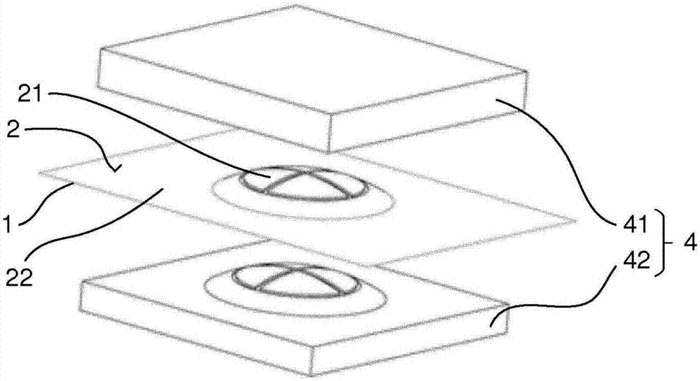
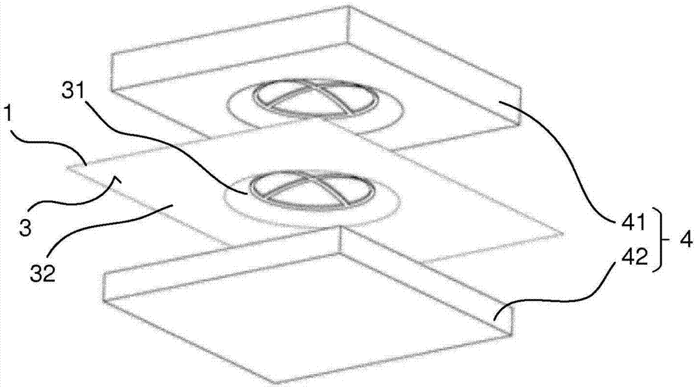
[0034] figure 1 and 2 The method for producing a decorative component with a raised embossed visible surface is shown in two different perspective views. The trim component is preferably an interior component of a vehicle.

[0035] In this method, a decorative material layer 1 and an embossing device 4 comprising a female embossing mold 41 and a male embossing mold 42 are provided. The negative embossing mold 41 and the positive embossing mold 42 are preferably made by additive manufacturing methods such as selective laser beam melting, selective laser sintering, stereolithography, multi-jet...


PUM

PropertyMeasurementUnit
elastic modulusaaaaaaaaaa
thicknessaaaaaaaaaa
elastic modulusaaaaaaaaaa

Abstract

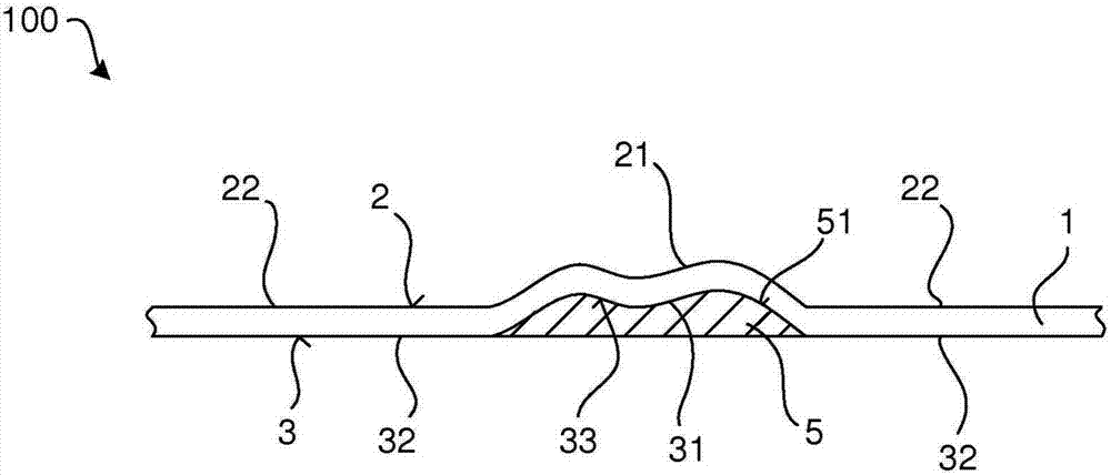
The invention relates to a method for manufacturing a decorative element (100) having a raised embossed visible surface (2). According to said method, an embossing device (4) having a female embossingdie (41) and a male embossing die (42) and at least one decorative material layer (1) are provided. Said decorative material layer (1) is disposed between the female embossing die (41) and the male embossing die (42) such that a visible surface of the decorative material layer (1) faces the female embossing die (41), and a backing surface (3) of the decorative material layer (1), opposite the visible surface (2), faces the male embossing die (42). The embossing is then carried out using the embossing device (4) such that the decorative material layer (1), after embossing, has a raised region(21) on the visible surface (2) and an opposite recessed region (31) on the backing surface (3). In order to stabilize the raised region (21), an insert element (5) is inserted in the recessed region(31). The invention further relates to a decorative element (100) manufactured according to the said method.

Description

technical field [0001] The invention provides a method for producing a decorative element with a raised embossed visible surface. The decorative component can be, for example, a layer of decorative material, in particular a layer of natural material made of leather or laminate. Furthermore, a decorative component produced by this method is specified. Background technique [0002] In order to emboss leather or textiles, it is usually clamped in a frame and placed under the press. The pattern is then imprinted into the workpiece under heat and pressure. The process parameters here determine the stability of the embossing. The higher the pressure and temperature or the higher the humidity of the leather, the more durable or finer the deformation of the material. [0003] To create a filigree texture in wood and / or leather, a so-called propane punch or a soldering iron is used. Here, a punch or a soldering iron is heated to the desired temperature and pressed into the mater...

Claims


Application Information

Patent Timeline
Patent Type & Authority Applications(China)
IPC IPC(8): B44C3/02B44C1/24B44B5/02C14B7/04C14B1/56
CPCB44B5/028B44C1/24C14B1/56B44C3/025B33Y10/00B33Y80/00B29C59/002B29L2031/722
Inventor M·弗里德里希D·里特泽尔S·兹格尔迈尔
Owner BAYERISCHE MOTOREN WERKE AG
Learn More