
Method for designing fluid flow engine and fluid flow engine

An engine casing and engine technology, applied to liquid fuel engines, parts of pumping devices for elastic fluids, engine components, etc., can solve the problems of reduced fluid flow engine efficiency, reduced rotor blade bearing capacity, etc., to achieve Reduced tip friction, small temperature effects, small centrifugal effects

Inactive Publication Date: 2018-01-02
SIEMENS AG
View PDF7 Cites 0 Cited by
  • Summary
  • Abstract
  • Description
  • Claims
  • Application Information

AI Technical Summary

Problems solved by technology

This reduces the load-carrying capacity of the rotor buckets, resulting in less efficient fluid flow engines

Method used


Image

  • Method for designing fluid flow engine and fluid flow engine
  • Method for designing fluid flow engine and fluid flow engine
  • Method for designing fluid flow engine and fluid flow engine

Examples


Embodiment Construction

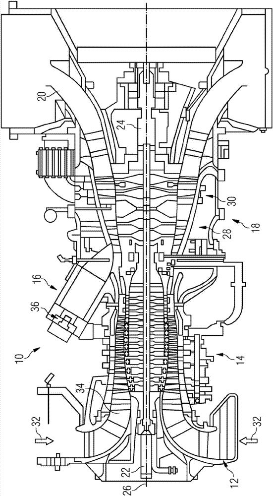
[0029] figure 1 is a schematic illustration of the general arrangement of a gas turbine engine 10 having an inlet 12 , a compressor 14 , a combustion system 16 , a turbine system 18 , an exhaust duct 20 and a dual shaft arrangement 22 , 24 . Gas turbine engine 10 is generally arranged about axis 26 , which is the axis of rotation of the rotating components. These arrangements 22, 24 may have the same or opposite directions of rotation.

[0030] The combustion system 16 includes an annular array of a plurality of combustion device units, ie, burners 36 , only one of which is shown. In one example, there are six combustors 36 evenly spaced around the generator 10 .

[0031] The turbine system 18 includes a high pressure turbine 28 which is drivingly connected to the compressor 14 via a first shaft 22 of a dual shaft arrangement 22 , 24 . The turbine system 18 also includes a low pressure turbine 30 which is drivingly connected to a load (not shown) via the second shaft 24 of ...


PUM


Abstract

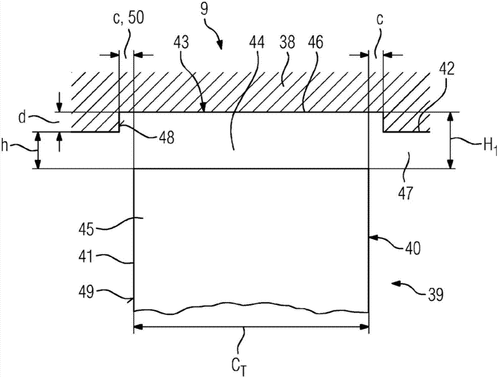
The invention relates to a fluid flow engine (9), in particular compressor or turbine of a gas turbine engine (10), having a stationary engine casing (38) and a rotor assembly (39) rotatable supportedin the engine casing (38). The rotor assembly (39) comprises at least one circumferentially extending rotor blade row (40) with a plurality of radially extending unshrouded rotor blades (41). An inner surface (42) of the engine casing (38) comprises at least one circumferentially extending slot (43) arranged radially outside of the rotor blade row (40). A gap (44) is provided between tips (45) ofthe rotor blades (41) and a base (46) of the slot (43), wherein the depth (d) of the slot (43) is less than the gap height of the gap (44).

Description

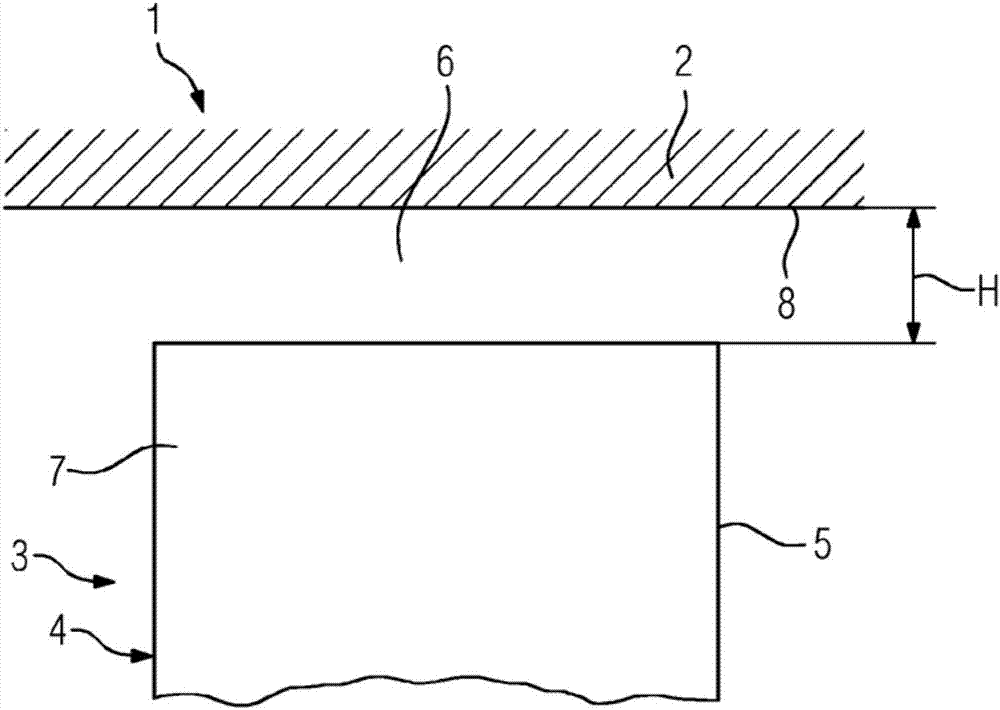
technical field [0001] The present invention relates to a method for designing a fluid flow engine, in particular a compressor or turbine for a gas turbine engine. [0002] Furthermore, the present invention relates to a fluid flow engine, in particular to a compressor or turbine of a gas turbine engine, having a stationary engine casing and a rotor assembly rotatably supported in the engine casing, the rotor assembly comprising at least a circumferentially extending rotor bucket row having a plurality of radially extending shroudless rotor buckets, the inner surface of the engine casing including at least one circumferentially extending slot disposed in said rotor The radially outer side of the row of buckets, wherein a gap is provided between the tips of the rotor buckets and the base of the slot. Background technique [0003] A fluid flow engine has a stationary engine housing and a rotor assembly rotatably supported within the engine housing. The rotor assembly include...

Claims


Application Information

Patent Timeline
Patent Type & Authority Applications(China)
IPC IPC(8): F01D5/20F01D11/08F01D11/14F04D29/16F04D29/52
CPCF01D5/20F01D11/08F04D29/526F04D29/164F01D11/14F01D5/142F04D17/08
Inventor S·克里施纳巴布
Owner SIEMENS AG
Learn More