Supercharge Your Innovation With Domain-Expert AI Agents!

Fixed ball valve, valve sealing structure and valve packing

A ball valve and sealing surface technology, applied in the field of fixed ball valves, can solve problems such as difficulty in ensuring tightness, large insertion force, and increased number of parts, and achieve the effects of preventing fluid leakage, improving tightness, and maintaining tightness

Active Publication Date: 2019-11-22
KITZ CORP
View PDF9 Cites 0 Cited by
  • Summary
  • Abstract
  • Description
  • Claims
  • Application Information

AI Technical Summary

Problems solved by technology

[0012] In the ball valve of the former Patent Document 1, in order to deform the packing material while pushing it into the wedge-shaped packing insertion part for insertion, a large insertion force is required, and especially in the case of a large diameter valve, it may be difficult to install. In, the surface pressure may not be exerted after loading
In addition, it is difficult to secure enough surface pressure necessary for sealing because the insertion force is intended to obtain most of the surface pressure of the packing and the shell, since the increase in the sealing surface pressure caused by the use of springs and fluid pressure is small.
[0013] With regard to the ball valve of the latter patent document 2, when the pressure fluid leaks from the contact portion between the packing material and the valve body, the metal seal ring is intended to prevent the pressure fluid from leaking to the downstream side. The protruding structure makes it necessary to process the wire diameter of the sealing ring and the tapered portion of the ring seat with high precision. If these dimensions are uneven, it is difficult to ensure the sealing performance
There is also a problem that the number of parts increases due to the installation of seal rings and gaskets

Method used


Image

  • Fixed ball valve, valve sealing structure and valve packing
  • Fixed ball valve, valve sealing structure and valve packing
  • Fixed ball valve, valve sealing structure and valve packing

Examples


Embodiment Construction

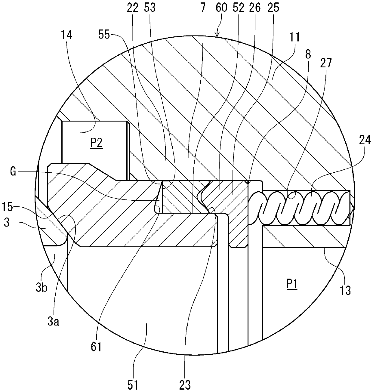
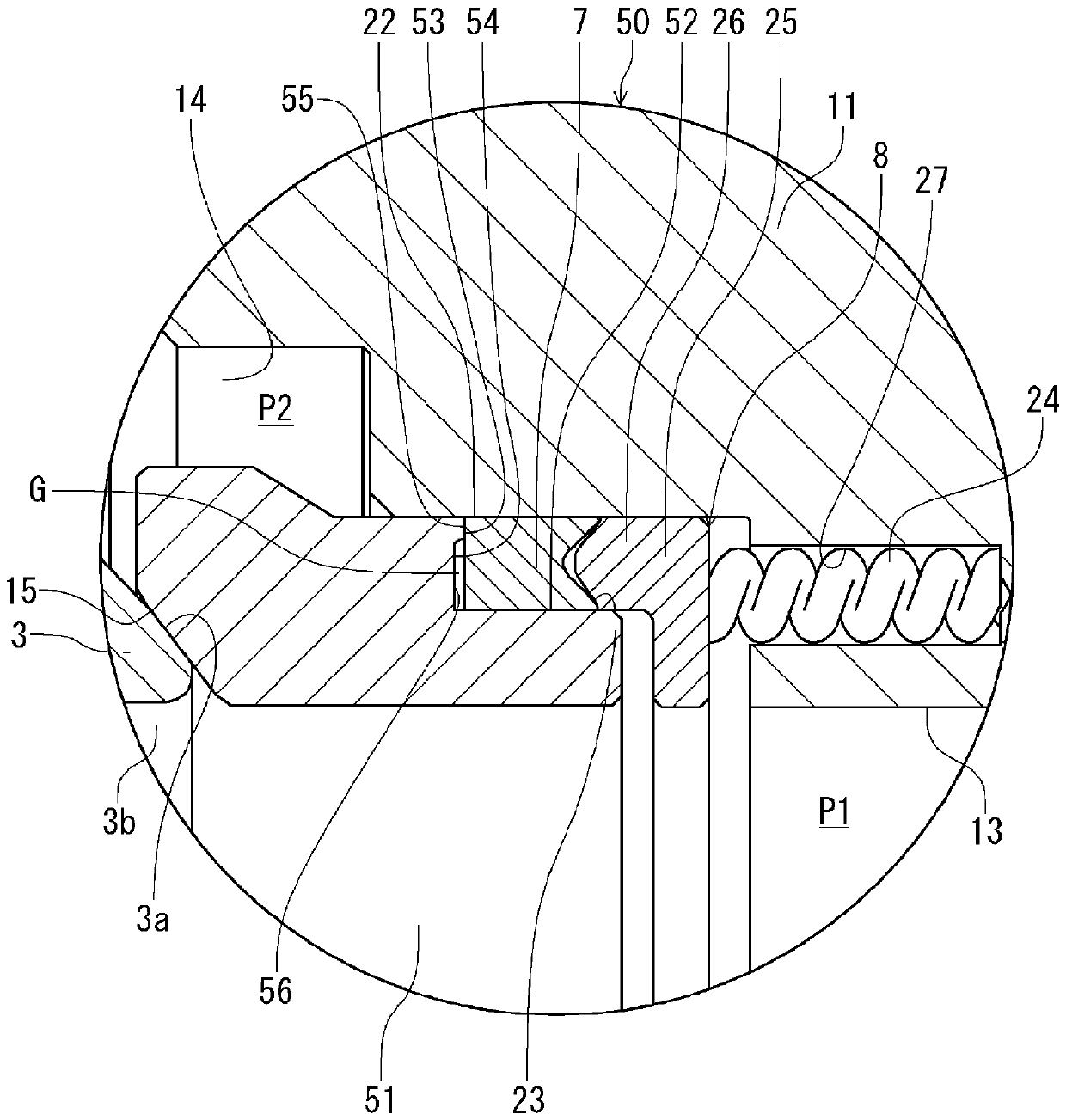
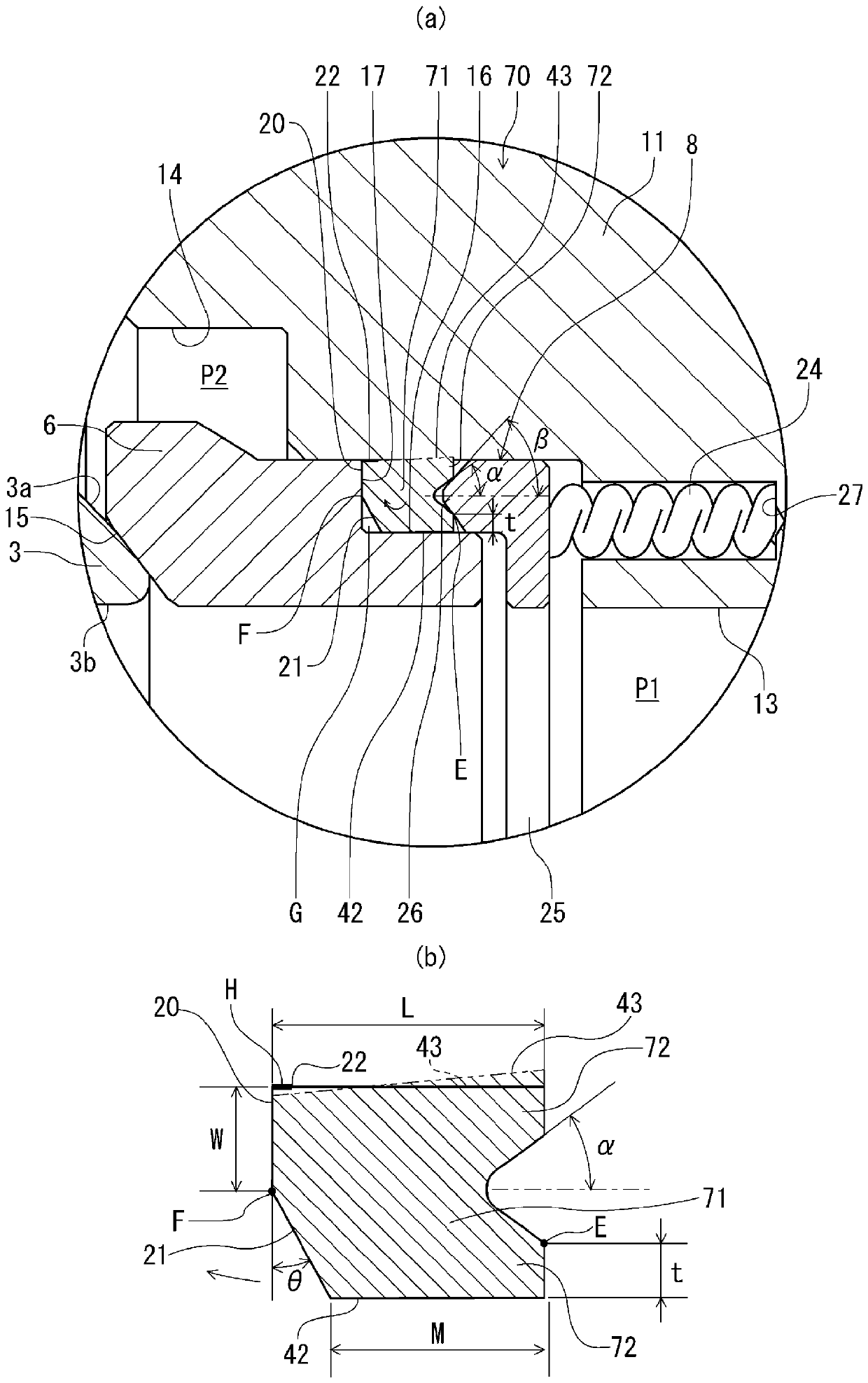
[0050] Hereinafter, embodiments of a fixed ball valve, a valve sealing structure, and a valve packing according to the present invention will be described based on the drawings. exist figure 1 The first embodiment of the fixed ball valve of the present invention is shown in figure 2 (a) means figure 1 An enlarged sectional view of part A.

[0051] figure 1 , figure 2 The fixed ball valve (hereinafter referred to as the valve main body 1) of (a) has a valve body 2, a ball 3, an upper valve stem 4, a lower valve stem 5, a ball seat 6, a packing body 7, and a pushing mechanism 8, and is particularly suitable for For use with high-pressure and high-temperature fluids. Specifically, for example, it is suitable for the use range of the highest working pressure: 10~25MPa, working temperature: -40°C~535°C, the valve main body 1 of this embodiment is assumed to have a working pressure of 10MPa, a working temperature of 400°C, and a nominal pressure of 600 pounds ( 10MPa), si...


PUM


Abstract

To provide a fixed ball valve, its sealing structure and valve packing, which can be assembled between the ball seat and the valve body in a tight state without packing the fixed ball valve, its sealing structure and valve packing. In particular, the sealing surface pressure at the outer peripheral part of the tip is increased to reliably prevent fluid leakage even under high pressure and high temperature, and the packing is assembled in a predetermined installation state without requiring high-precision processing and adjustment of the compression amount. The ball (3) provided in the valve body (2) is rotatably provided via the upper and lower stems (4, 5), and is sealed by a ball seat (6) which contacts the ball (3) in a pressed state. It has a filler (7) and a pushing mechanism (8), the aforementioned filler (7) is assembled between the outer peripheral step (16) and the valve body (2), and the aforementioned outer peripheral step (16) is set on the ball seat (6 ), the aforementioned pushing mechanism (8) pushes the stuffing (7) toward the ball (3), and the outer diameter side of the end of the aforementioned stuffing (7) has a step surface with the outer peripheral step (16). (17) The contact surface (20) in contact has a space (G) provided between the stepped surface (17) of the outer peripheral stepped portion (16) on the inner diameter side of the tip of the filler (7), at least by means of a pushing mechanism The pushing force of (8) increases the sealing surface pressure at the outer peripheral portion of the tip of the packing (7).

Description

technical field [0001] In particular, the present invention relates to a fixed ball valve with a structure suitable for high pressure and high temperature, a sealing structure of the valve, and a packing for the valve. Background technique [0002] Conventionally, as a valve used in a high-pressure and high-temperature environment, for example, a fixed ball valve is known. In this valve, a seat usually used as a valve seat is assembled on the valve body, and the seat is springed toward the valve body by the elastic force of a spring assembled between the valve body and the retainer gland, and is pushed against the valve body. The ball valve body is arranged so as to be able to close the fluid with the seat on the upstream side. [0003] In this case, in order to improve the sealing performance of the seat and the valve body, a packing material is installed between them. As packing materials for high-pressure and high-temperature applications, those made of expanded graphit...

Claims


Application Information

Patent Timeline
Patent Type & Authority Patents(China)
IPC IPC(8): F16K5/06
CPCF16K5/20F16K5/0689F16K5/06F16K5/0678F16K5/0605F16K5/0647F16K5/201F16K27/067
Inventor 风间正裕船渡正澄
Owner KITZ CORP
Features
  • R&D
  • Intellectual Property
  • Life Sciences
  • Materials
  • Tech Scout
  • Unparalleled Data Quality
  • Higher Quality Content
  • 60% Fewer Hallucinations
Learn More