
Power assembly for hybrid vehicle and combined type speed changer of power assembly

A technology for hybrid vehicles and transmissions, which is applied to the layout of multiple prime movers of hybrid vehicles and general-purpose power plants, and motor vehicles. Good performance and economy, and the effect of improving the effective utilization rate

Inactive Publication Date: 2018-01-05
SCHAEFFLER TECH AG & CO KG
View PDF0 Cites 2 Cited by
  • Summary
  • Abstract
  • Description
  • Claims
  • Application Information

AI Technical Summary

Problems solved by technology

[0008] The problem to be solved by the present invention is: the existing powertrain for hybrid vehicles needs to use two motors, resulting in an increase in the cost of the motors, wherein one motor is used as a power source, and the other motor uses the power of the internal combustion engine to generate power to charge the battery

Method used


Image

  • Power assembly for hybrid vehicle and combined type speed changer of power assembly
  • Power assembly for hybrid vehicle and combined type speed changer of power assembly
  • Power assembly for hybrid vehicle and combined type speed changer of power assembly

Examples


no. 1 example

[0034] Powertrain for Hybrid Vehicles

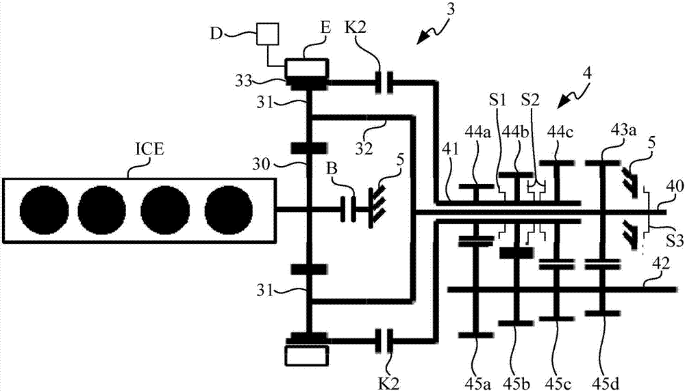
[0035] Such as figure 1 As shown, the powertrain of the hybrid vehicle in this embodiment includes an internal combustion engine ICE, a motor E, and a combined transmission (not marked). The internal combustion engine ICE and the motor E are used as power sources, and the output power is transmitted to the wheels through the combined transmission.

[0036] In this embodiment, the internal combustion engine ICE takes a four-cylinder engine as an example. In a modified example of the present embodiment, the internal combustion engine ICE may be an engine with another number of cylinders.

[0037] In the technical solution of the present invention, in addition to being used as a power source (working in the motor mode), the motor E is also used as a generator to convert the power output by the internal combustion engine ICE into electrical energy and store it in the battery D. Regarding how the motor E will The conversion of the power o...

no. 2 example

[0121] Powertrain for Hybrid Vehicles

[0122] One of the differences between the second embodiment and the first embodiment is that in the second embodiment, as Figure 4 As shown, the combined transmission further includes a second power coupling unit K1. One end of the second power coupling unit K1 is connected to the planetary gear 31 and the other end is connected to the planet carrier 32 , and can be switched between an engaged state and a disengaged state. When the second power coupling unit K1 is in the engaged state, torque transmission between the planetary gear 31 and the planetary carrier 32 is established. When the second power coupling unit K1 is in the disengaged state, the torque transmission between the planetary gear 31 and the planetary carrier 32 is interrupted.

[0123] The second difference between the second embodiment and the first embodiment is that in the second embodiment, as Figure 4 As shown, there are two first gears on the first input shaft...


PUM


Abstract

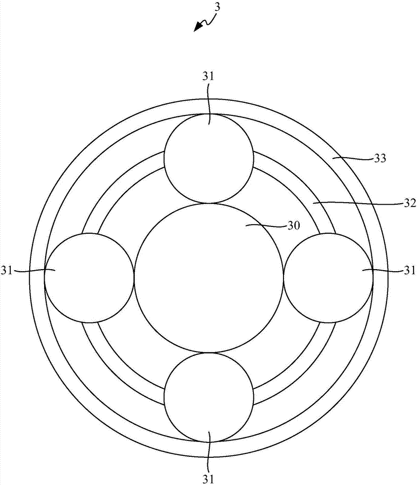
The invention provides a power assembly for a hybrid vehicle and a combined type speed changer of the power assembly. The speed changer comprises a planetary gear set, a parallel-axle type speed changer unit, a plurality of gears of gear pairs, a first power coupling unit and a first locking unit. The planetary gear set comprises a sun gear, a planet gear, a planet frame and a gear ring. The parallel-axle type speed changer unit comprises a first input shaft, a second input shaft and an output shaft, and the axial end of the first input shaft is in torsional connection with the planet frame. The multiple gears of gear pairs are arranged on the first input shaft, the second input shaft and the output shaft in a sleeving mode. One end of the first power coupling unit is connected with the gear ring, the other end of the first power coupling unit is connected with the second input shaft, and the first power coupling unit can be switched between the joint state and the separated state. Thefirst locking unit is connected with the sun gear, and used for locking or releasing the sun gear. The number of motors needed by the power assembly is reduced by half, and thus the cost of the motors is lowered.

Description

technical field [0001] The invention relates to the technical field of hybrid electric vehicles, in particular to a power assembly for a hybrid electric vehicle and a combined transmission thereof. Background technique [0002] Hybrid vehicles combine an internal combustion engine, an electric motor and a battery, which can take advantage of the advantages of internal combustion engine vehicles and electric vehicles, and are one of the effective technical ways to reduce oil consumption and carbon dioxide emissions. [0003] A powertrain for a hybrid vehicle includes an internal combustion engine, a first electric machine, a second electric machine and a planetary gear set. Wherein, both the internal combustion engine and the second electric motor are used as power sources for driving the vehicle, and the first electric motor is used not only as a generator to charge the battery, but also as an electric motor to start the internal combustion engine. [0004] The planetary ge...

Claims


Application Information

Patent Timeline
Patent Type & Authority Applications(China)
IPC IPC(8): B60K6/365B60K6/44
CPCY02T10/62
Inventor 狄杰梅近仁
Owner SCHAEFFLER TECH AG & CO KG
Learn More